Soundproofing panel for turbomachine and turbomachine comprising such a panel

Active Publication Date: 2013-10-01
SN DETUDE & DE CONSTR DE MOTEURS DAVIATION S N E C M A
View PDF17 Cites 14 Cited by
  • Summary
  • Abstract
  • Description
  • Claims
  • Application Information

AI Technical Summary

Benefits of technology

The invention is a soundproofing panel that reduces assembly and fastening requirements. It uses a radial fastening flange that allows for mounting with longitudinal fastening means without damaging the air blower. The panel is supported at its downstream end to increase assembly accuracy.

Problems solved by technology

Besides, thanks to the radial fastening flange, the panel can be mounted with longitudinal fastening means without the need of radial fastening means susceptible to damage the operating air blower.

Method used


Image

  • Soundproofing panel for turbomachine and turbomachine comprising such a panel
  • Soundproofing panel for turbomachine and turbomachine comprising such a panel
  • Soundproofing panel for turbomachine and turbomachine comprising such a panel

Examples


first embodiment

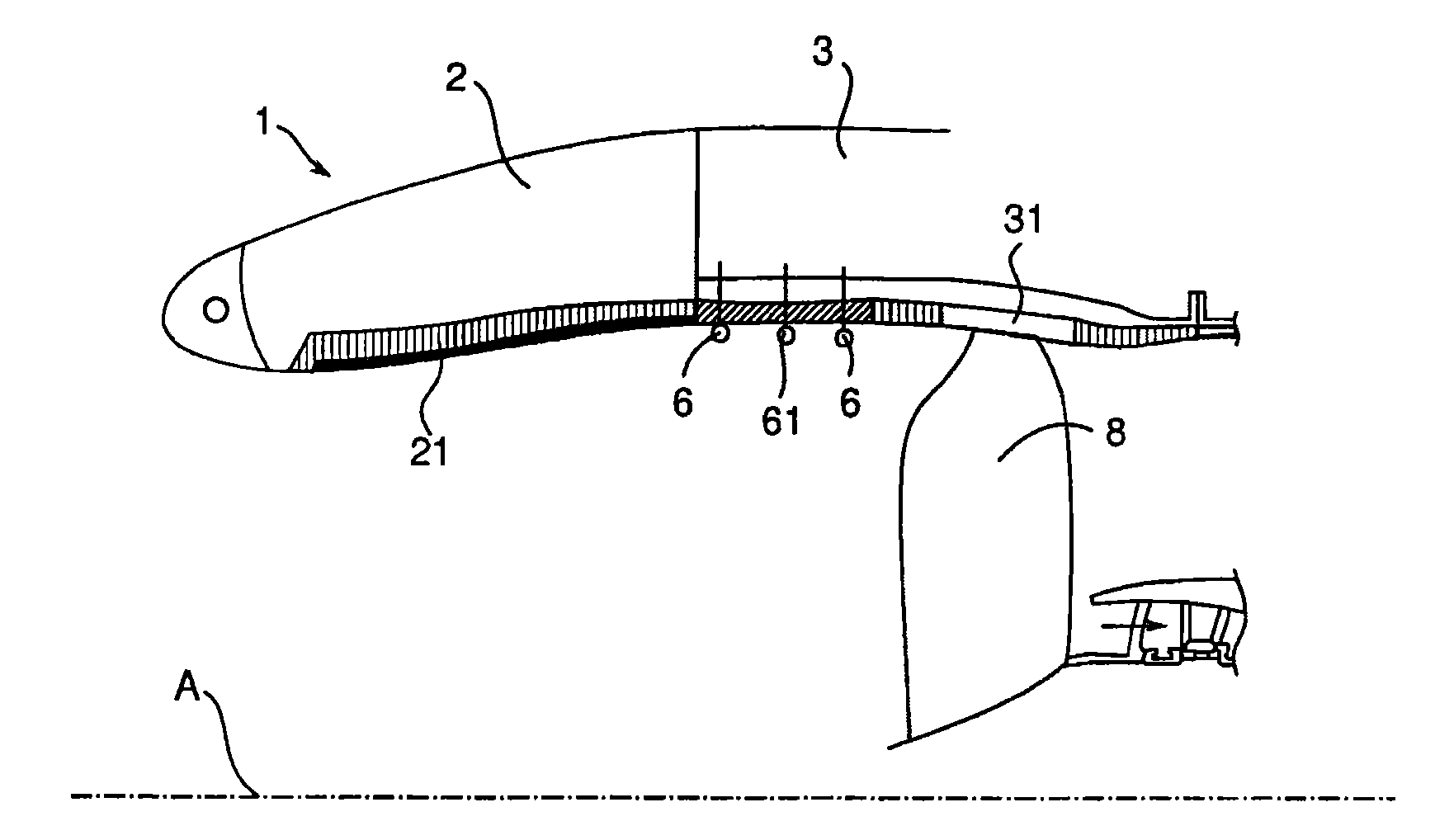
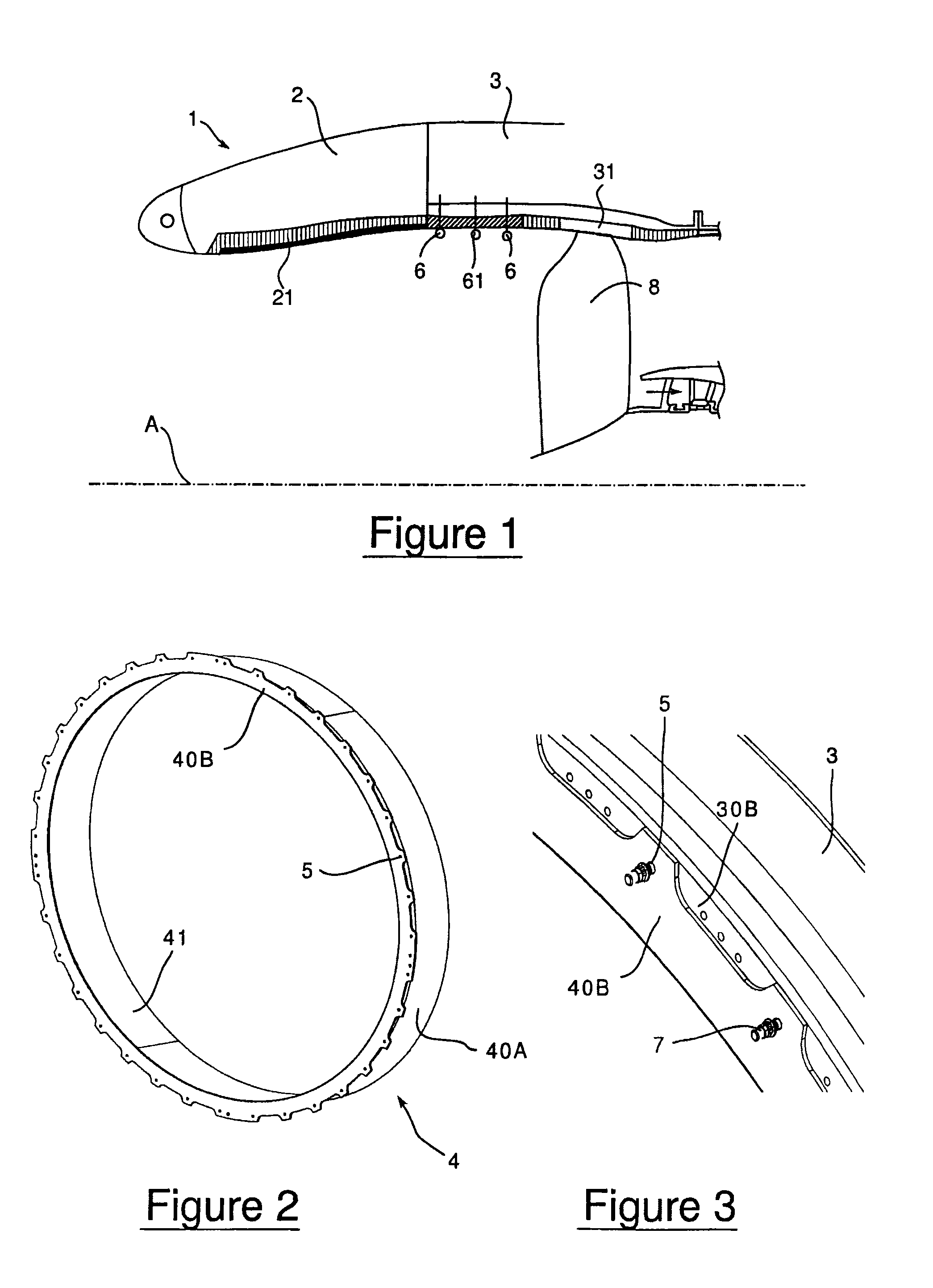
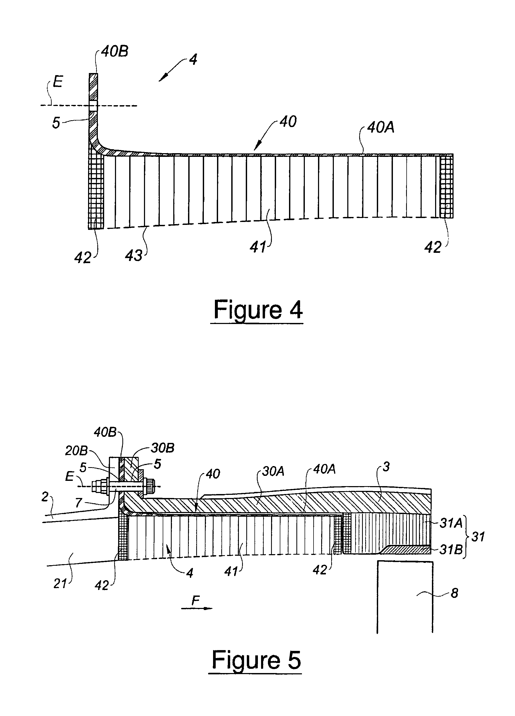
[0081]According to the insulation panel 4, in reference to FIG. 4, this last one does not comprise support means provided at its downstream end, the insulation panel 4 being only maintained upstream by the fastening flange 40B.

[0082]In the following embodiments represented from the FIG. 7A, the turbomachine comprises support means of the downstream end of the soundproofing panel 4 in the air blower casing 3 to improve the fastening and the assembly of the acoustic panel 4 in the turbomachine.

[0083]Such support means allow to distribute the fastening regions of the soundproofing panel between its upstream and downstream ends. Advantageously, it allows to decrease the axial thickness of the fastening flange 40B and so to decrease its mass. The support means of the turbomachine can be only formed on an element of the air blower casing or on an element of the air blower casing and the insulation panel. The element of air blower casing 3 has to be understood as a structural element as we...

second embodiment

[0086]an insulation panel 4, represented in FIGS. 7A-7C, presents a downstream end on which is formed an annular tongue 91 intended to fit into an annular groove 92 formed in an element of the air blower casing 3.

[0087]Referring more particularly to FIG. 7A, the tongue 91 of the soundproofing panel 4 is formed in the acoustic coating 41 of the panel 4 by division of the downstream reinforcement region 42 of the acoustic coating 41, preferably, of its radially inwardly part as shown in FIG. 7A.

[0088]The groove 92 is formed between the internal surface of the air blower casing 3 and an annular tongue 93, formed in the downstream annular layer 31 of the air blower casing 3 by division of its upstream reinforcement region 42, preferably of its radially inwardly part as shown in FIG. 7A.

[0089]The assembly of the soundproofing panel 4 is realized by insertion of the panel 4 from upstream towards downstream so that the tongue 91 of the panel 4 is received in the groove 92 so that the panel...

third embodiment

[0091]Referring to FIGS. 8A to 8B representing an insulation panel 4 according to the invention, similarly to the previous embodiment, the downstream end of the soundproofing panel 4 comprises an annular tongue 91′ mounted in an annular groove 92′ formed between the internal surface of the air blower casing 3 and an annular tongue 93′ formed in the downstream annular layer 31 of the air blower casing 3. In this example, the tongue 92′ of the panel 4 has a radial thickness greater to that of the tongue 93′ of the air blower casing 3 as shown in FIG. 8A. As example, the radial thickness of the tongue 93′ of the downstream annular layer 31 of the air blower casing 3 is approximately 2 mm whereas the radial thickness of the tongue 91′ of the panel 4 is approximately 30 mm. So, the radial thickness of the acoustic coating 41 of the panel 4 remains essentially constant along its length which improves the soundproofing of the turbomachine.

[0092]Advantageously, the annular tongue 93′ of the...


PUM

PropertyMeasurementUnit
Thicknessaaaaaaaaaa

Abstract

A one-piece soundproofing panel which is attached within an circumferential air blower casing of a turbomachine, with an axis, in which circulates an airflow from upstream to downstream, is disclosed. The panel includes a circumferential rigid seat with a longitudinal cylindrical part, arranged to axially extend with respect to the axis A of the turbomachine, having an outside surface, intended to come to extend facing with an internal surface of the air blower casing, and an internal surface to which is applied a soundproofing coating; and an annular fastening flange, formed at the upstream end of the longitudinal cylindrical part, radially outwardly extending, the fastening flange being arranged to cooperate with a fastening flange of the air blower casing.

Description

BACKGROUND OF THE INVENTION[0001]1. Field of the Invention[0002]The present invention relates to the field of soundproofing of an aircraft turbomachine and, more particularly, soundproofing upstream to an air blower for a turbomachine.[0003]2. Description of the Related Art[0004]A turbomachine such as an engine turbojet or an aircraft turboprop typically comprises an annular casing for the air blower, axially extending along the turbomachine axis, in which an air blower is mounted, i.e., a rotor disc comprising large size blades. In operation, an airflow circulates from upstream to downstream within the turbomachine. For an aircraft propulsion, the turbomachine is mounted inside an engine nacelle integral with an aircraft wing. Typically, the engine nacelle comprises an annular inlet duct which is mounted upstream the air blowing casing. Referring to FIG. 1 representing a cross sectional half-view of a turbomachine 1 having axis A, soundproofing panels 21, 61 are traditionally mount...

Claims


Application Information

Patent Timeline
IPC IPC(8): B64D33/02
CPCB64D33/02F02C7/045F01D25/243B64D2033/0206F05B2250/283F05B2260/30F05B2260/962F05D2260/30F05D2260/962F05D2250/283Y02T50/672Y02T50/60Y10T29/49236
Inventor GAUDRY, FLORIANPLANTE, ROMAINROBIN, NOELRIOU, GEORGES JEAN XAVIERMARDJONO, JACKY NOVIMARLIN, FRANCOIS MARIE PAUL
Owner SN DETUDE & DE CONSTR DE MOTEURS DAVIATION S N E C M A
Why Eureka
Try Eureka