Cardiovascular imaging system

a technology of imaging system and heart muscle, applied in the field of cardiac imaging system, can solve the problems of reduced blood and oxygen flow to the heart muscle, chest pain, and limitations of fluoroscopy,

Active Publication Date: 2013-10-01
SPECTRANETICS
View PDF102 Cites 16 Cited by
  • Summary
  • Abstract
  • Description
  • Claims
  • Application Information

AI Technical Summary

Problems solved by technology

When the blockage is severe, the flow of blood and oxygen to the heart muscle is reduced, causing chest pain.
Fluoroscopy, however, has limitations.
For example, does not allow a doctor or technician to visualize plaque or vessel walls.

Method used


Image

  • Cardiovascular imaging system
  • Cardiovascular imaging system
  • Cardiovascular imaging system

Examples


Embodiment Construction

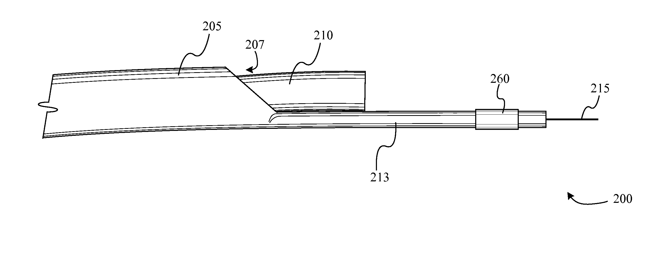
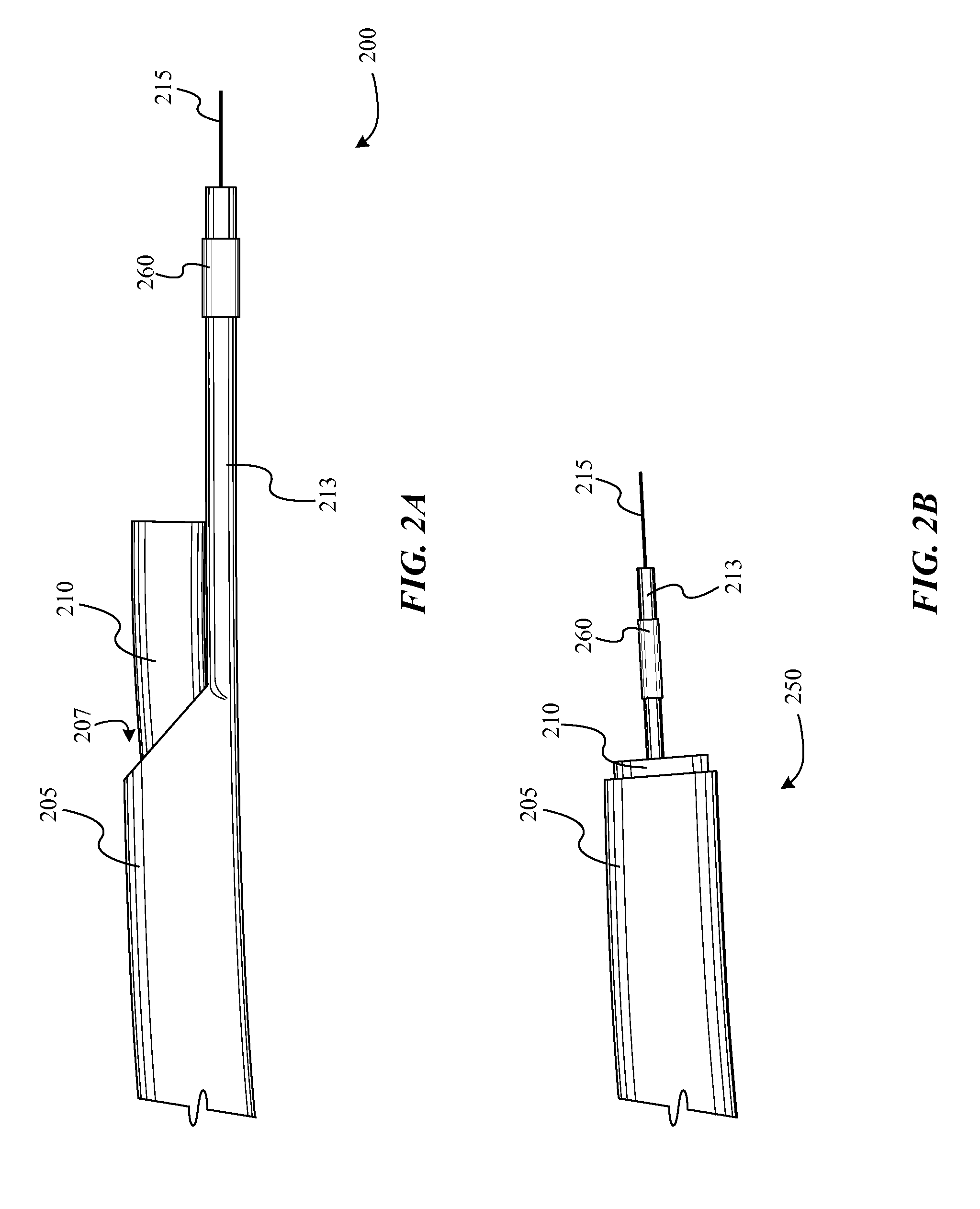
[0036]Embodiments of the present invention include a laser catheter that employs an imaging device. In some embodiments, the imaging device is disposed distal (or forward) relative to the exit aperture of the laser catheter. In some embodiments, the laser catheters can employ gating techniques to ensure that laser pulses don't interfere with imaging. Other embodiments include laser catheters that include balloons or ramps that can deflect the exit aperture of the laser catheter.

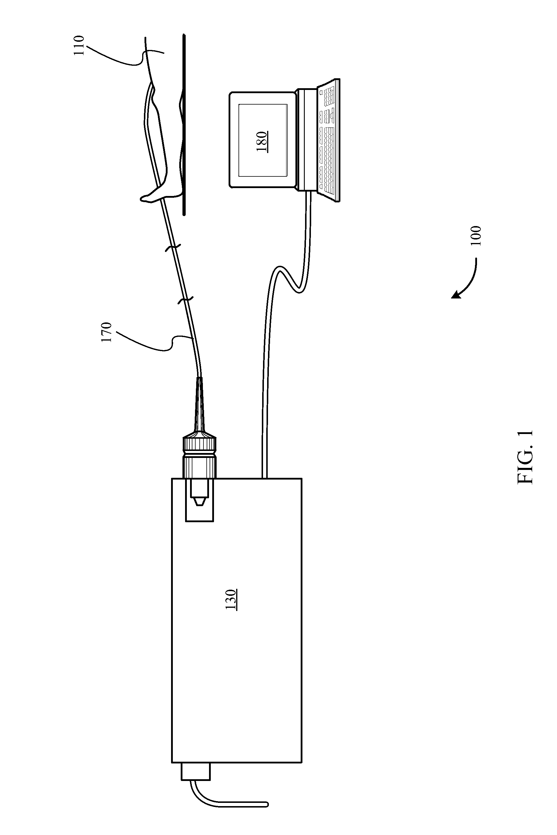
[0037]FIG. 1 shows a laser catheter system 100 in use according to one embodiment. A laser 130 is shown coupled with a user interface 180. In this embodiment the user interface 180 is computer programmed to control the laser 130. The laser, for example, may be an excimer laser. The laser, for example, may also produce light in the ultraviolet range. The laser is connected with a catheter 170 that may be inserted into a vessel of the human body 110. The laser catheter system 100 may employ one or more tapered ...


PUM


Abstract

Embodiments of the present invention include a laser catheter that includes a catheter body, a light guide, and a distal tip that extends beyond the exit aperture of the light guide. In some embodiments, an imaging device is disposed on the distal tip such that the imaging device is distal relative to the exit aperture of the light guide. In some embodiments, the imaging device can be gated to record images during and / or slightly beyond periods when the laser catheter is not activated.

Description

CROSS-REFERENCES TO RELATED APPLICATIONS[0001]This application is a continuation in part of U.S. Non-Provisional application Ser. No. 12 / 337,232 filed on Dec. 17, 2008, which is a continuation in part of U.S. Non-Provisional application Ser. No. 11 / 228,845 filed on Sep. 16, 2006, which claims the benefit of U.S. Provisional Application Ser. No. 60 / 611,191 filed Sep. 17, 2004. Each of these disclosures are incorporated by reference in their entirety.BACKGROUND[0002]Arteries are the primary blood vessels that are responsible for providing blood and oxygen to the heart muscle. Arterial disease occurs when arteries become narrowed or blocked by a buildup of plaque (as some examples, atherosclerotic plaque or other deposits). When the blockage is severe, the flow of blood and oxygen to the heart muscle is reduced, causing chest pain. Arterial blockage by clots formed in a human body may be relieved in a number of traditional ways. Drug therapy, including nitrates, beta-blockers, and peri...

Claims


Application Information

Patent Timeline
Patent Type & Authority Patents(United States)
IPC IPC(8): A61B18/18
CPCA61B18/245A61B8/12A61B2017/22038A61B2017/22061A61B2018/2238A61B2019/5278A61B2090/3782
Inventor TAYLOR, KEVIN D.HARLAN, KENNYE, JAMESSPLINTER, ROBERTKEELER, JACOBHEBERT, CHRIS J.BOWE, WADE A.
Owner SPECTRANETICS
Why Eureka
Try Eureka