Pipe mapping system

a mapping system and pipe technology, applied in the field of pipe mapping systems, can solve the problems of high cost and prone to failure of the usual slip ring assembly, the difficulty of precisely determining the underground position of the inspection assembly with a remote locator, and the frame and axle that rotatably supports the reel also represent additional bulk and expense, so as to improve the information display format and system, and improve the cable counting method

Active Publication Date: 2013-10-01
SEESCAN
View PDF26 Cites 130 Cited by
  • Summary
  • Abstract
  • Description
  • Claims
  • Application Information

AI Technical Summary

Benefits of technology

[0010]This invention provides an advantageous enhancement to pipe inspection systems by, for the first time, integrating multiple local condition sensors with the camera head assembly in the pipe inspection assembly and by providing an improved information display format and system, an improved cable-counting method, and improved methods for detecting, analyzing and relaying data for determining camera location and environment in real time during a pipe inspection. This invention also, for the first time, provides a system and method for generating a three-dimensional (3D) pipe mapping image on a display in real time from data received from a pipe inspection assembly.

Problems solved by technology

The usual slip ring assembly is expensive and prone to failure.
The frame and axle that rotatably support the reel also represent additional bulk and expense.
Heretofore the signals radiated from such transmitters have been inherently weak, making it difficult to precisely determine the underground position of the inspection assembly with a remote locator.
Most existing systems may provide a disoriented video image whenever the camera head assembly rotates away from alignment with the longitudinal axis of the pipe being inspected because of such issues as uncontrolled push cable torque or navigation through a bend or joint in the pipe.
Existing systems provide no means for tracking changes in camera orientation and distance traversed in the subject pipe or conduit nor to generate a map of the pipe from camera travel distances and headings.

Method used


Image

  • Pipe mapping system
  • Pipe mapping system
  • Pipe mapping system

Examples


embodiment 99

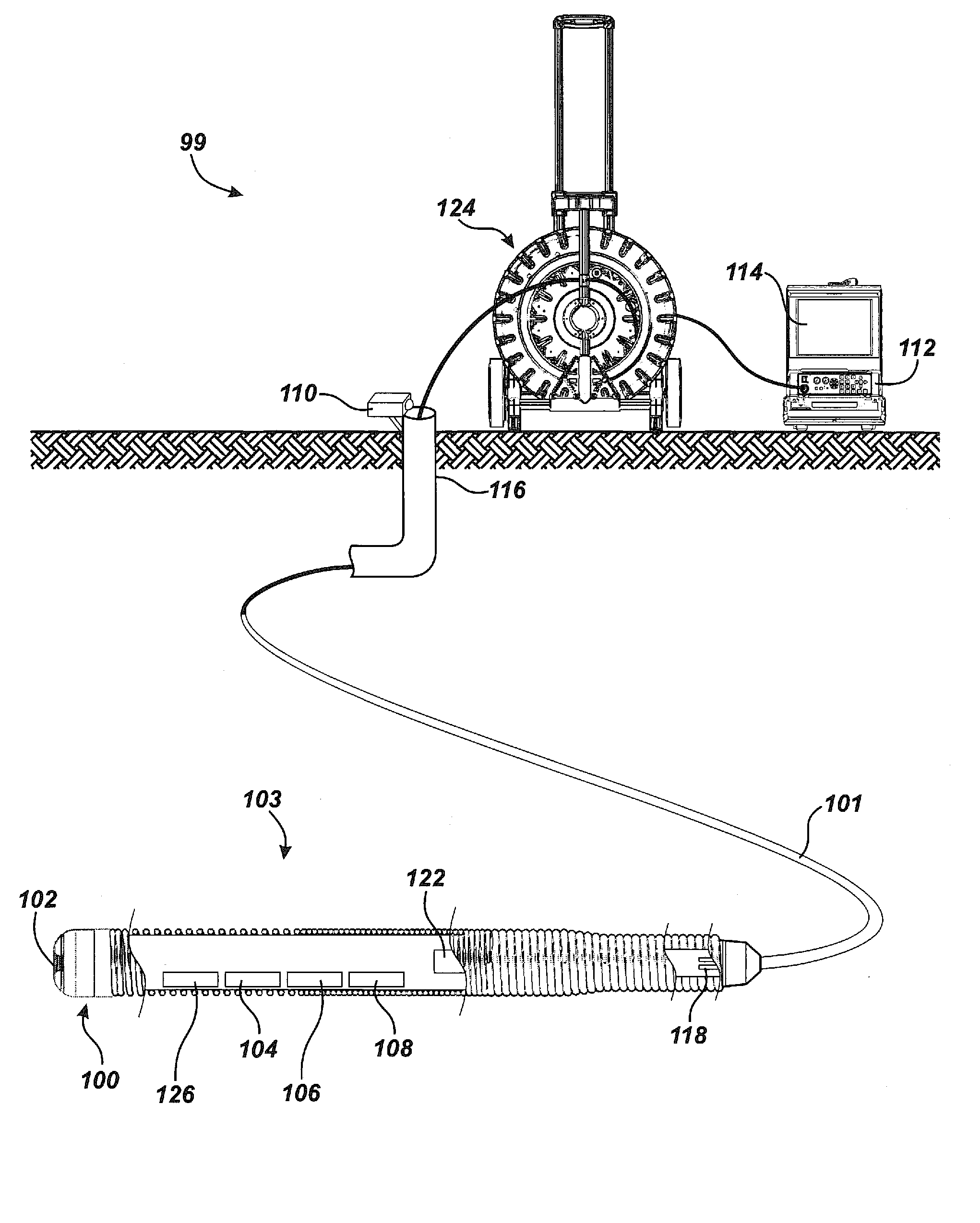
[0076]FIG. 1 is a schematic diagram illustrating an exemplary pipe mapping system embodiment 99 showing a pipe inspection assembly 103 having an inspection camera head assembly 100 incorporating an image sensor 102, and also having a three-axis compass 108, a three-axis accelerometer 126, a three-axis gyroscopic (“gyro”) sensor 104, and a temperature sensor 106, each for producing a sensor data signals responsive to the respective local physical condition. Pipe inspection assembly is coupled to a push cable 101, which is stored and extended from the cable storage drum unit 124 proximate to a cable counter 110 for counting the length in feet or meters of push cable 101 extending into a pipe 116 under inspection. Image sensor 102 is disposed at the front of camera head assembly 100 (at the very front of inspection assembly 103) so that the field of view (FOV) of image sensor 102 includes the entire circumference of the adjacent interior pipe wall (not shown). Local condition sensor da...

embodiment 300

[0078]This invention includes a method of capturing complete pointing vector information for individual images at different instants in time that facilitates the generation of a tracking map and a three-dimensional (3D) representation of the pipe during inspection. An inspection path track image may be displayed with the camera head image, for example. FIG. 3A is a block diagram illustrating a processing flow embodiment 300 of accelerometer data 316, compass data 328, gyro data 319, and cable counter data 318. The accelerometer data 316 are combined with the magnetic compass data 328 to produce a camera head assembly pointing vector 322, which is then associated with the current cable counter step increment 318. It may be reasonably assumed that the inspection camera pointing direction is approximately parallel with the axis of the pipe under inspection when moving therein. A cable counter value 318, accelerometer data 316, gyro data 319, and compass data 328 are sent to the system ...

embodiment 501

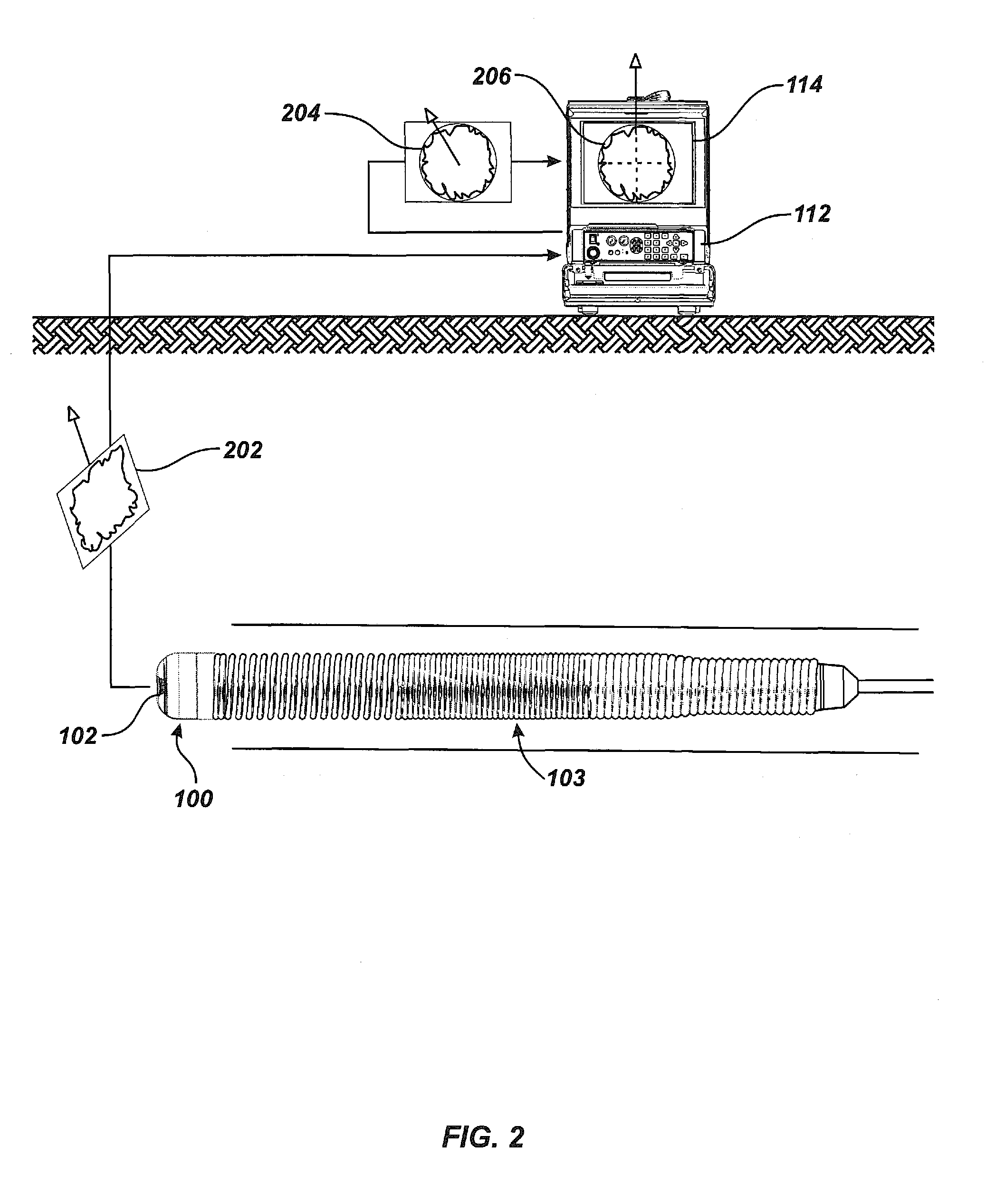
[0084]The system of this invention may include a dipole Sonde attached to or near the inspection assembly or integrated therewith to facilitate operator measurement of camera depth below ground at any moment. FIG. 5A is a schematic diagram of a pipe mapping system embodiment 501 in which the depth (A) 504 of the inspection assembly 503 below some reference surface, such the earth's surface 505, is measured by using an electromagnetic Sonde locator 500 to locate a Sonde 122 in or adjacent to the inspection camera head assembly 100. The locator's computed measurement depth (A) 504 from ground level 505 to the integral Sonde 122 is shown. Locator 500 is disposed at the ground level 505 above a buried pipe 116 in which a push-cable 101 affixed to the inspection assembly 503 incorporating the integral Sonde 122 and camera head assembly 100 with image sensor 102 (FIG. 1) is disposed as it is during inspection of pipe 116. A removable cable count device 110 is affixed to the head of pipe 1...


PUM


Abstract

A pipe inspection system employing a camera head assembly incorporating multiple local condition sensors, an integral dipole Sonde, a three-axis compass, and a three-axis accelerometer. The camera head assembly terminates a multi-channel push-cable that relays local condition sensor and video information to a processor and display subsystem. A cable storage structure includes data connection and wireless capability with tool storage and one or more battery mounts for powering remote operation. During operation, the inspection system may produce a two- or three-dimensional (3D) map of the pipe or conduit from local condition sensor data and video image data acquired from structured light techniques or LED illumination.

Description

CROSS-REFERENCE TO RELATED APPLICATIONS[0001]This application claims the benefit, pursuant to 35 USC Sections 119 and 120, of the filing date of U.S. Provisional Application Ser. No. 60 / 864,104 filed Nov. 2, 2006 naming Mark S. Olsson and David A. Cox as co-inventors and entitled “Pipe Mapping System.”BACKGROUND[0002]1. Field of the Invention[0003]This invention relates generally to electronic and mechanical systems and methods for inspecting the interior of pipes and other conduits.[0004]2. Description of the Related Art[0005]There are many situations where it is desirable to internally inspect long lengths of pipe that are already in place, either underground, in a building, or underwater. For example, sewer and drain pipes frequently must be internally inspected to diagnose any existing problems and to determine if there are any breaks causing leakage or obstructions impairing the free flow of waste. It is also important to internally inspect steam pipes, heat exchanger pipes, wa...

Claims


Application Information

Patent Timeline
Patent Type & Authority Patents(United States)
IPC IPC(8): H04N5/253
CPCG03B37/005H04N5/232H04N2005/2255G01C15/00H04N23/555H04N23/63G06T7/0004H04N7/185G06T15/04G06T17/05G06T2207/10016G06T2207/10028G06T2207/30108H04N23/60G01N21/8803
Inventor OLSSON, MARK S.COX, DAVID A.
Owner SEESCAN
Why Eureka
Try Eureka