
Cooling device for Stirling circulated dry storage container

a technology of circulated dry storage and cooling device, which is applied in the direction of machines/engines, nuclear engineering, light and heating apparatus, etc., can solve the problems of affecting people start doubting the wet storage method, etc., and achieve the effect of enhancing the entire heat dissipation efficiency

Inactive Publication Date: 2013-10-15
INST NUCLEAR ENERGY RES ROCAEC
View PDF8 Cites 3 Cited by
  • Summary
  • Abstract
  • Description
  • Claims
  • Application Information

AI Technical Summary

Benefits of technology

The present invention provides a cooling device for a Stirling circulated dry storage container. The device uses residual heat from high radiation level waste as the heat source and drives the rotation of an electric fan through a Stirling engine. This helps to enhance the entire heat dissipation efficiency. The device is economically efficient, stable, and reliable. It is important to note that the residual heat can be fully used to drive the Stirling engine, and no additional electrical energy is needed.

Problems solved by technology

However, after Mar. 11, 2011, for the Fukushima nuclear plant of Japan, strong earthquake has caused the loss of cooling circulation power in the cooling water of the used fuel pool, and the fuel rods thus got melted and H2 generation is triggered due to the dissolution of Zirconium alloy, hence, people start doubting about the wet storage method which uses the fuel pool for the cooling; hence, after long term cooling of the used fuel rods in the fuel pool, the fuel rods are moved out, and dry storage method is adopted next for the rest of the storage, and this has become the major promotional policy of the nuclear industry in countries around the world.
However, it is an active heat dissipation system, which needs a driving device.
However, during the real application of this structure, since the peripheral is an open space, the electric fan that is driven by Stirling engine will not have good air circulation path during its operation, turbulent effect could easily be generated to affect the entire heat dissipation efficiency.

Method used


Image

  • Cooling device for Stirling circulated dry storage container
  • Cooling device for Stirling circulated dry storage container
  • Cooling device for Stirling circulated dry storage container

Examples


Embodiment Construction

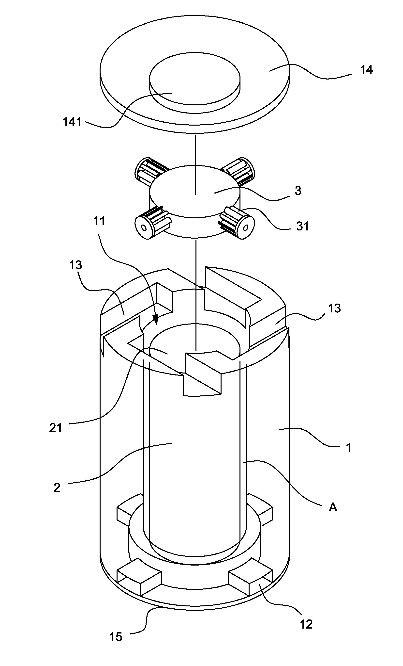
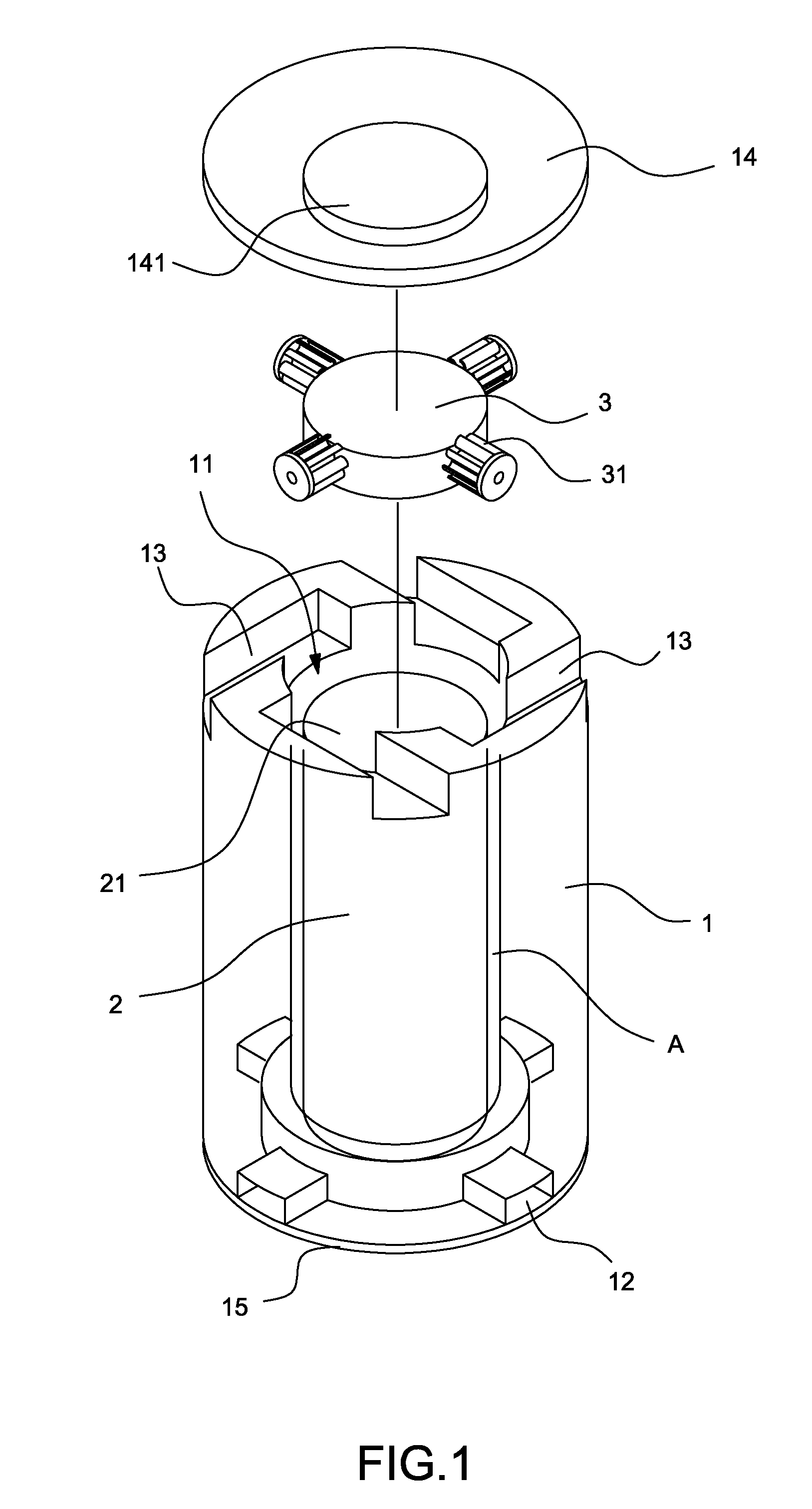
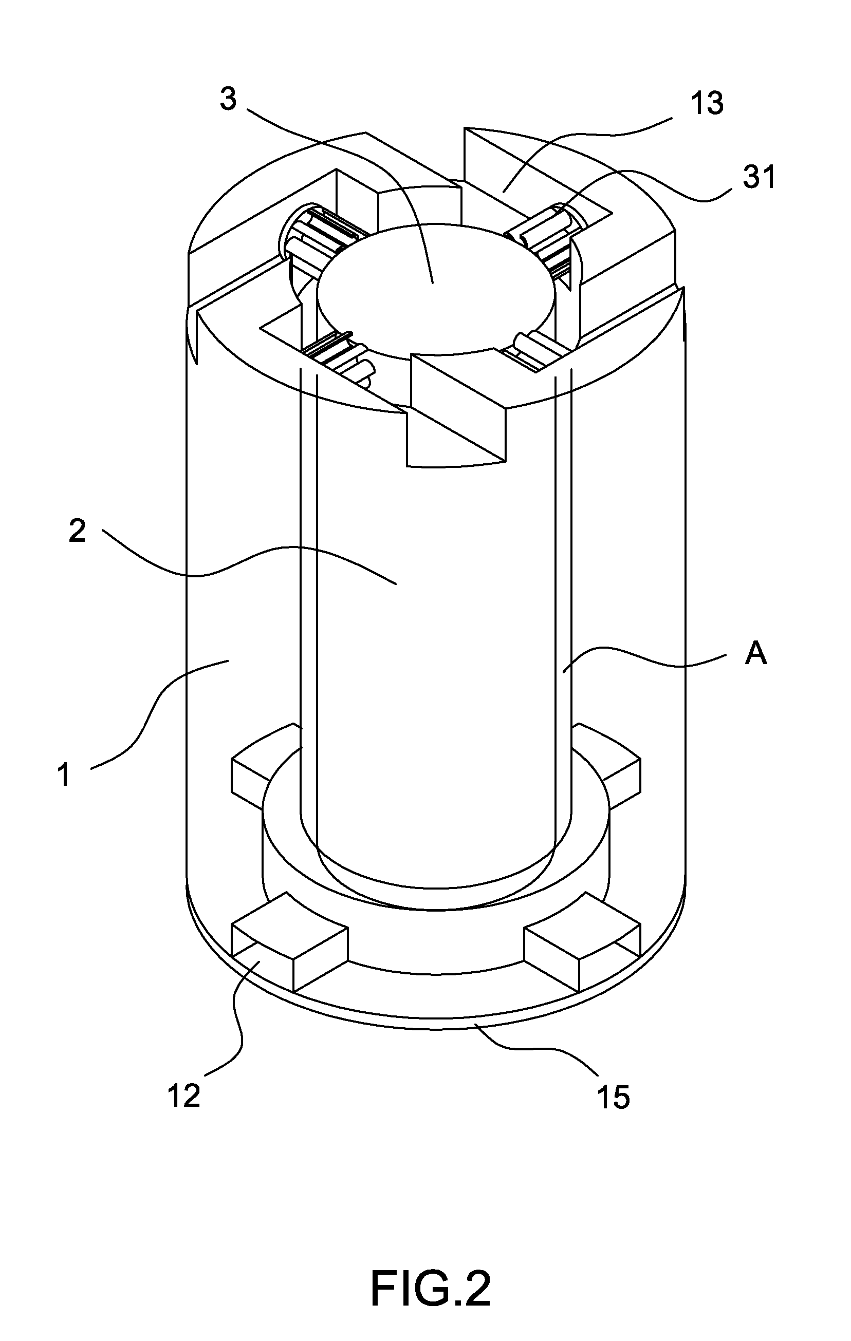
[0026]By referring to FIGS. 1 to 3, it can be seen that the structures of the present invention mainly include:

[0027]External shield 1, nuclear waste storage container 2 and Stirling heat engine 3; wherein external shield 1 is structural body that is precast by cement, at its inside, it is installed with accommodation space 11 that has opening on the top side, at the peripheral of the bottom of the accommodation space 11, it is installed with a plurality of air flow inlets 12 that extend in radiated way to the external side, at the peripheral of the top side of accommodation space 11, it is installed with a plurality of air flow outlets 13 that extend along the tangent direction to the external side; in addition, a cement precast shield cover 14 can cover on the opening of the accommodation space 11, and at the center of the shield cover 14, it is installed with a protruding part 141 that can extend into accommodation space 11, and at the bottom surface of the external shield 1, it ...


PUM


Abstract

A cooling device for Stirling circulated dry storage container, which is mainly to make an accommodation space with opening within an external shield, and at the peripherals of the accommodation space, it is installed with a plurality of air flow inlets and air flow outlets that are connected to the external side. In addition, a shield cover is used to cover the opening of the accommodation space, and a nuclear waste storage container is installed within the accommodation space of the external shield, and the peripheral of the accommodation space and the nuclear waste storage container forms an air flow channel.

Description

BACKGROUND OF THE INVENTION[0001]1. Field of the Invention[0002]The present invention relates to a cooling device of Stirling circulated dry storage container, and it specifically means a cooling device that does not need the additional supply of power, has economic efficiency, and can operate stably for a long time.[0003]2. Description of the Prior Art[0004]For the processing of high radiation level waste such as used nuclear fuel, currently in the world's nuclear electricity industry for the initial stage (within five years), spent fuel pool is adopted to accommodate the high radiation level waste; however, after five years, it enters the medium processing stage, and the medium processing stage can be divided into wet storage and dry storage methods. In the wet storage method, high level radiation waste is continuously placed in the cooling system of spent fuel pool so as to use the same method to cool continuously the high level radiation waste, however, in dry cask storage, sinc...

Claims


Application Information

Patent Timeline
Patent Type & Authority Patents(United States)
IPC IPC(8): G21D5/00
CPCG21F5/10F02G1/055F02G2254/90
Inventor LIN, YAN-TINGCHIU, PAO-HSIUNG
Owner INST NUCLEAR ENERGY RES ROCAEC
Learn More