
Terahertz antenna arrangement

a technology of terahertz antennas and antennas, applied in the direction of non-resonant long antennas, antennas, electrically long antennas, etc., can solve the problem of emitted broadband radiation with frequencies up to the thz range, and achieve the effect of improving performan

Inactive Publication Date: 2013-10-15
NOVATRANS GRP SA
View PDF5 Cites 6 Cited by
  • Summary
  • Abstract
  • Description
  • Claims
  • Application Information

AI Technical Summary

Benefits of technology

This configuration results in improved radiation efficiency and polarization of the radiated field, allowing for more effective terahertz radiation generation and reception, with enhanced performance in the 0.5 THz to 3 THz frequency band, and increased radiation density due to focused laser irradiation.

Problems solved by technology

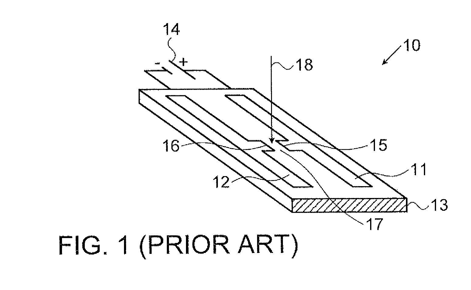
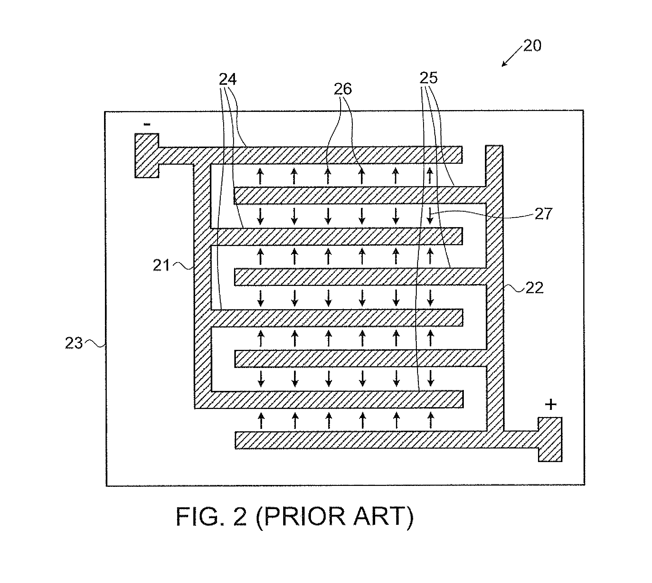
When a bias voltage is applied to the electrodes, a photogenerated current flows between the electrodes, which in turn results in the emission of broadband radiation with frequencies up to the THz range.

Method used


Image

  • Terahertz antenna arrangement
  • Terahertz antenna arrangement
  • Terahertz antenna arrangement

Examples


Embodiment Construction

[0040]The principles and operation of an interdigital antenna arrangement according to the present invention may be better understood with reference to the drawings and the accompanying description, it being understood that these drawings are given for illustrative purposes only and are not meant to be limiting. Examples of constructions, materials, dimensions, and manufacturing processes are provided for selected elements. Those versed in the art should appreciate that many of the examples provided have suitable alternatives which may be utilized.

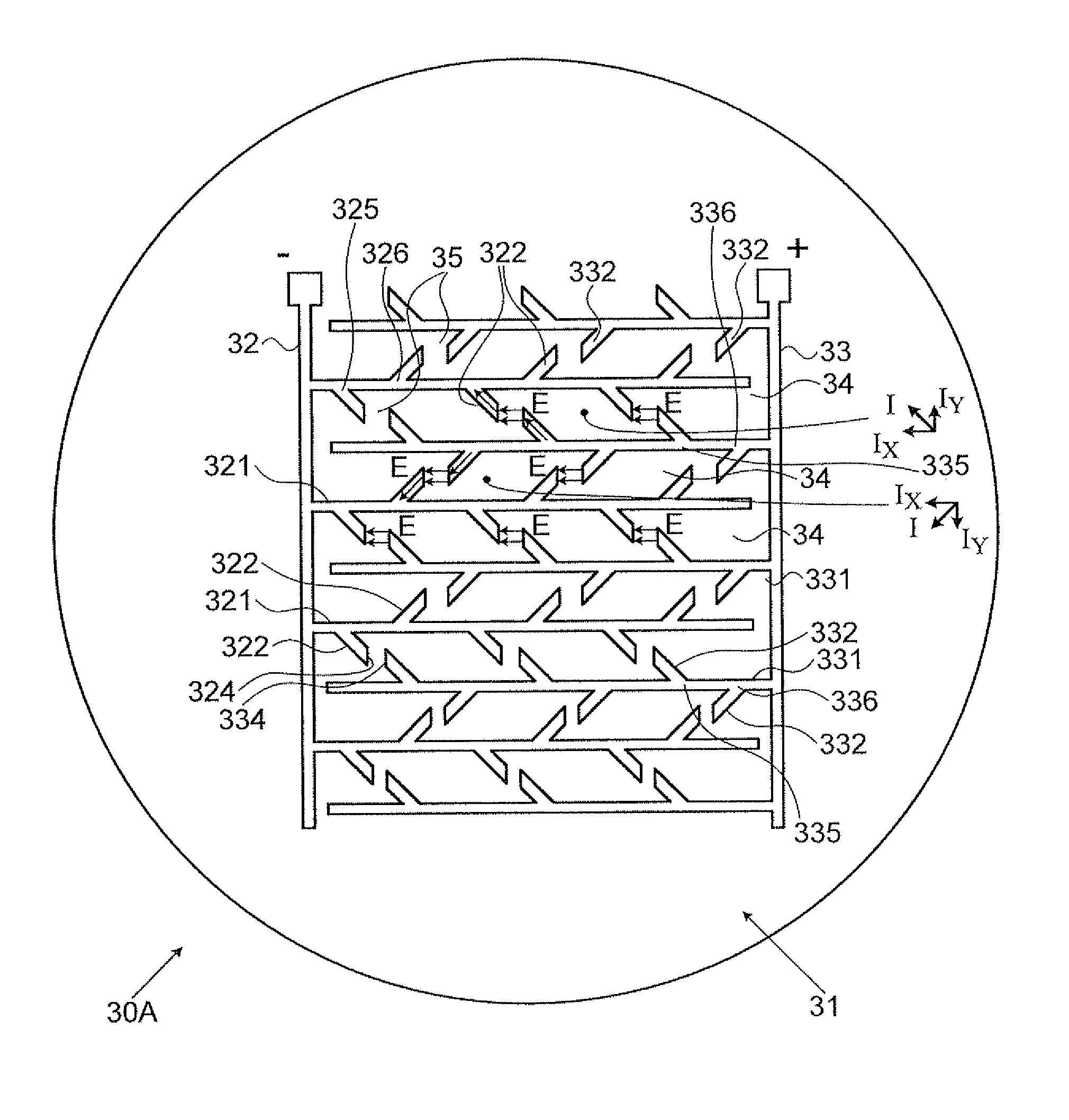
[0041]Referring now to the drawings wherein like reference numerals designate corresponding parts throughout the several views, FIG. 3A illustrates a schematic view of an antenna arrangement 30A according to one embodiment of the present invention. It should be noted that this figure as well as further figures (illustrating other examples of the antenna of the present invention) are not to scale, and are not in proportion, for purposes of ...


PUM


Abstract

An antenna arrangement for generating and receiving terahertz radiation is described. The arrangement comprises a substrate comprising a photoconductive material and a pair of electrodes provided on the photoconductive material. Each electrode includes a plurality of elongate fingers spaced apart from each other which are arranged in a parallel relation and define finger gaps therebetween. The fingers of one electrode are located within the finger gaps formed between the spaced apart fingers of another electrode so that two neighboring fingers belong to different electrodes. The fingers of each electrode have at least one protrusion extending away from lateral sides of the fingers within the finger gap. Each protrusion is slanted with respect to the corresponding finger direction, and directed towards a neighboring slanted protrusion extending from the neighboring finger such that end edges of the neighboring protrusions extending from the neighboring fingers approximately face one another, thereby defining a protrusion gap between end edges of the facing protrusions.

Description

FIELD OF THE INVENTION[0001]The present invention relates generally to devices for generating and receiving electromagnetic radiation, and in particular, to an interdigital antenna arrangement for generating and receiving terahertz (THz) frequency range radiation.BACKGROUND OF THE INVENTION[0002]There are many applications using terahertz (THz) frequency range radiation. For example, THz radiation can be used for characterization of a variety of properties of solid and liquid materials, such as photoconductivity, dispersion, absorption, refractive index, etc. THz radiation can penetrate dry, non-metallic and non-polar objects like plastic, paper, textiles, cardboard, semiconductors and non-polar organic substances, therefore THz radiation can be used for safe package inspection instead of x-rays, e.g., to look inside boxes, cases etc. THz radiation can also be used for industrial process control, food inspection, biology and medicine.[0003]THz radiation may be generated or detected ...

Claims


Application Information

Patent Timeline
Patent Type & Authority Patents(United States)
IPC IPC(8): H01Q19/06
CPCH01Q1/38H01Q9/005
Inventor HABIB, LAURENTDAISY, RON
Owner NOVATRANS GRP SA
Learn More