Vehicle with pneumatic tire and method for cooling tire in the vehicle

a technology of pneumatic tires and tires, which is applied in the direction of vehicle cleaning, lighting and heating apparatus, brake discs, etc., can solve the problems of large heat generation, excessive tire vertical spring constant, so as to improve durability and prolong service life. the effect of the constant of vertical springs

Inactive Publication Date: 2013-10-22
SUMITOMO RUBBER IND LTD
View PDF22 Cites 7 Cited by
  • Summary
  • Abstract
  • Description
  • Claims
  • Application Information

AI Technical Summary

Benefits of technology

[0012]In the first and second objects of the present invention, the tire during running at low air pressure can be cooled with using a fluid. Therefore, without increasing excessively the vertical spring constants of the tire and the like, the heat generation of the tire during running with low air pressure can be delayed, and eventually the durability can be improved. In particular, when the pneumatic tire is a run flat tire, a running distance of run flat proceeding and / or a speed of run-flat running are pronouncedly increased.BRIEF EXPLANATION OF THE DRAWING
[0013]FIG. 1 A planar pattern diagram of a vehicle showing an embodiment of the present invention.
[0014]FIG. 2 An enlarged view of a substantial part near the front-right wheel thereof.
[0015]FIG. 3 A cross-sectional view taken along line A-A in FIG. 2.
[0016]FIG. 4 A cross-sectional view of the pneumatic tire showing the present embodiment.
[0017]FIG. 5 A planar pattern diagram of the vehicle showing another embodiment of the present invention.

Problems solved by technology

In a tire, running causes periodical distortion in a rubber portion.
In particular, when the tire keeps running with decreased air pressure, each strain becomes large, and much of heat generates.
When a rubber temperature of the tire exceeds a certain value, the rubber fracture begins.
In this run flat tire, even at a time of puncture for example, the side reinforcing rubber layer receives a tire load instead of air pressure, and eventually a deflection of the sidewall portion is limited.

Method used


Image

  • Vehicle with pneumatic tire and method for cooling tire in the vehicle
  • Vehicle with pneumatic tire and method for cooling tire in the vehicle
  • Vehicle with pneumatic tire and method for cooling tire in the vehicle

Examples


embodiment

A Case that the Fluid to Cool the Tire is a Liquid

[0093]Next, another embodiment of the present invention on a case that a fluid to cool the tire is a liquid will be described with reference to the figures from FIG. 7.

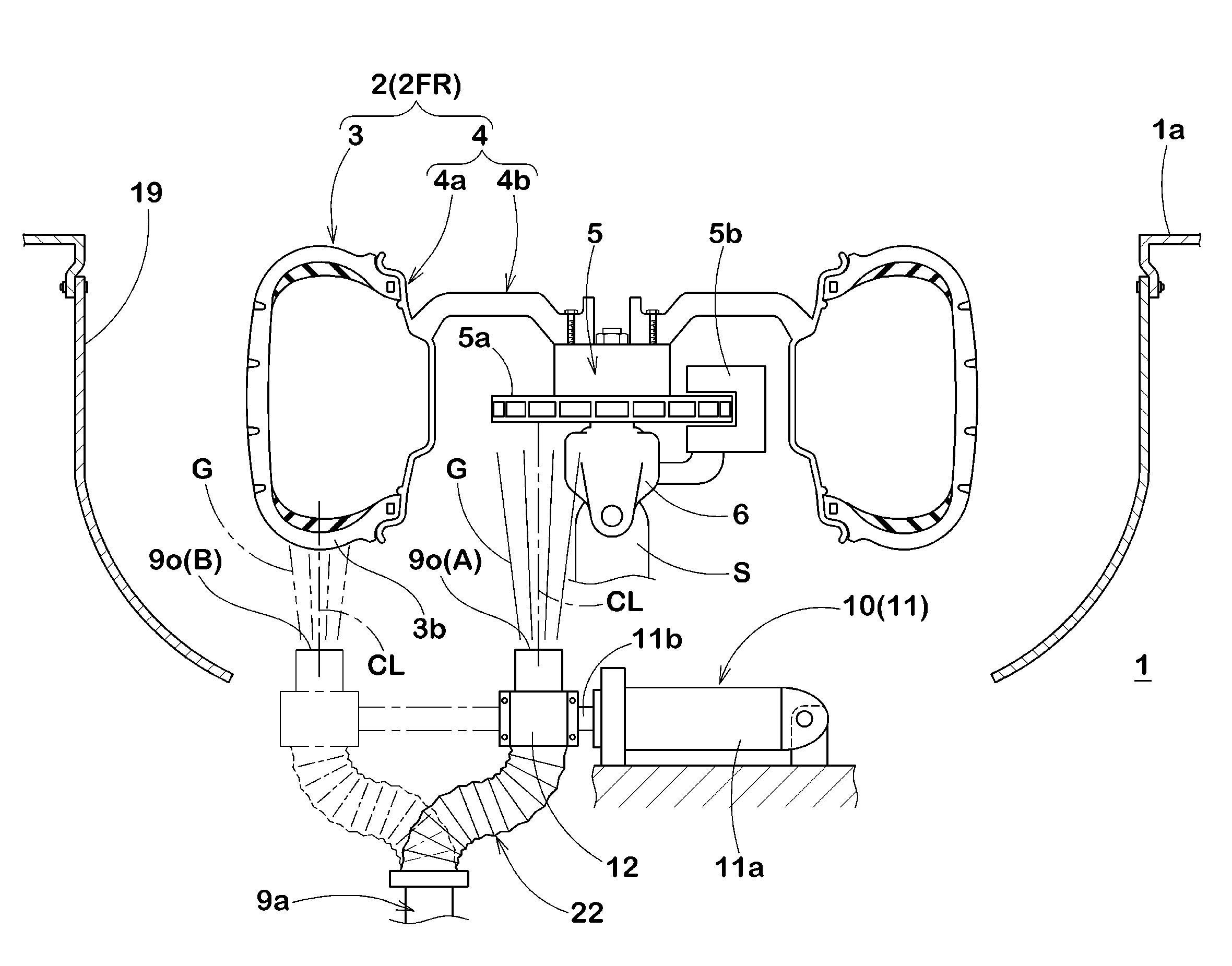
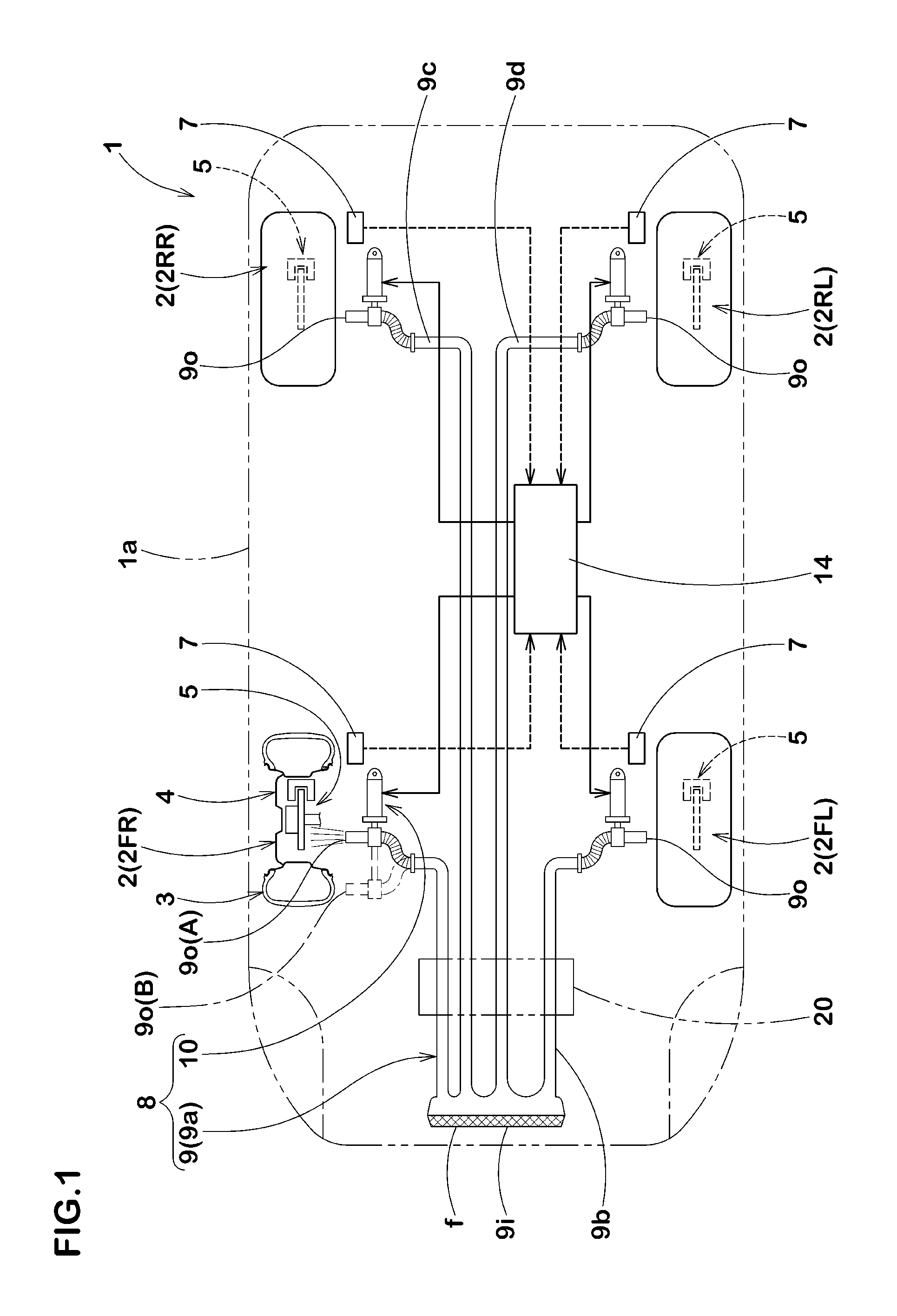
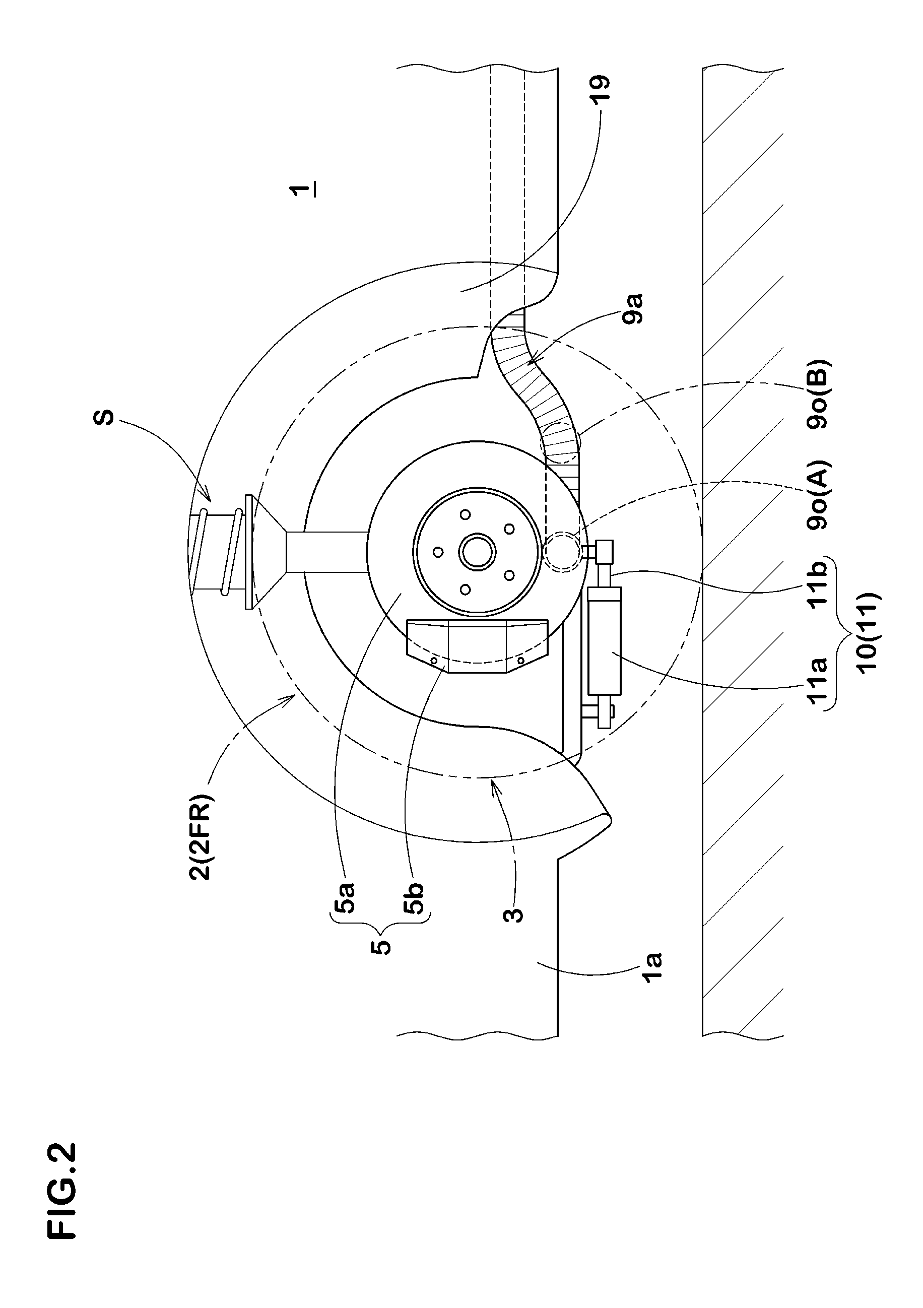
[0094]FIG. 7 shows a planar pattern diagram of the vehicle 1 concerning the present embedment. FIG. 8 shows a side view of a front-left wheel 2FL, and FIG. 9 shows a cross-sectional view taken along line A-A thereof, respectively. In the present embodiment, the vehicle 1 is provided with a cooling unit 8 which expels the liquid L to cool the pneumatic tire 3 from the outside thereof when the air pressure of the pneumatic tire 3 decreases. Also, excepting the cooling unit 8 and the controlling device 14, the same parts as the above-mentioned embodiment are assigned the same symbolic names without going into details.

[0095]The cooling unit 8 can expel the liquid L to the tire 3 running at low air pressure from the outside thereof so as to remove the heat thereof. Therefor...

example 1

Example of that a Fluid is Gas

[0131]In order to confirm an effect of the present invention, using the following vehicle, run-flat running tests were conducted. The specifications of the vehicle were as follows:

[0132]Displacement volume: 4300 cc, a rear-wheel drive vehicle manufactured in Japan

[0133]Tire (each wheel): a run-flat-type pneumatic tire having a size of 245 / 40R18

[0134]Front wheel load: 5.29 kN

[0135]Rear wheel load: 5.39 kN

[0136]Front wheel camber angle: 1 deg. (negative)

[0137]cooling unit equipped.

[0138]Moreover, in a run-flat running test, the front-right wheel got into a punctured state with air pressure of zero (the other three tires had an air pressure of 230 kPa). The car continuously ran at an average running speed of 80 km / h on a test course of a drying asphalt road surface for high speed running (weather: sunny; Air temperature: 24 deg. C.). A run-flat running distance until destruction of the tire was studied.

[0139]In the vehicle according to Example 1, a cooling...

example 2

Example of that a Fluid is Liquid

[0143]As an embodiment shown in FIGS. 7 to 9, a run-flat running test was conducted with the following vehicle. The specification of the vehicle was the same as the above.

[0144]Moreover, in a run-flat running test as with the above, the front-right wheel got into the punctured state with inner pressure of zero (the other three tires had an air pressure of 230 kPa). The car continuously ran at an average running speed of 80 km / h on the test course of the drying asphalt road surface for high speed running (weather: sunny; Air temperature: 24 deg. C.). A run-flat running distance until destruction of the tire was studied.

[0145]In the vehicle according to Example 2, the cooling unit was put into operation during test running so as to expel water at a temperature of about 25 deg. C. at high pressure for about three minutes every 10 km (Quantity per expelling: 200 cm3) toward the tread portion of the tire.

[0146]In contrast, in conventional Example, no cool...


PUM


Abstract

The first invention relates to a vehicle with pneumatic tires characterized in that the vehicle comprises a cooling unit which expels a fluid to cool the pneumatic tire from the outside thereof at least when the air pressure of the pneumatic tire decreases. And, the second invention relates to a tire cooling method in the vehicle with pneumatic tires comprising: a step of monitoring the air pressure of the pneumatic tire during running, and a step of expelling a fluid toward the pneumatic tire so as to cool the pneumatic tire from its outside when the air pressure falls below a predetermined value.

Description

TECHNICAL FIELD[0001]The present invention relates to a vehicle with pneumatic tires and a method for cooling tires in the vehicle, particularly to technology capable of improving durability during running at low air pressure of pneumatic tire.BACKGROUND OF THE INVENTION[0002]In a tire, running causes periodical distortion in a rubber portion. A part of the energy thereof is converted into heat, and the tire produces heat. In particular, when the tire keeps running with decreased air pressure, each strain becomes large, and much of heat generates. When a rubber temperature of the tire exceeds a certain value, the rubber fracture begins. Therefore, it is useful in enhancing durability of the tire to keep the temperature of the running tire down.[0003]And, in recent years, a run flat tire is prevalent for the purpose of enhancing convenience and safety and enlarging a vehicle interior space. It is well known that the run flat tire is of a side-reinforced type in which an inside of eac...

Claims


Application Information

Patent Timeline
Patent Type & Authority Patents(United States)
IPC IPC(8): B60C23/19F28D15/00
CPCB60C23/18
Inventor HINO, HIDEHIKO
Owner SUMITOMO RUBBER IND LTD
Why Eureka
Try Eureka