Gasification apparatus and method for generating syngas from gasifiable feedstock material

a gasification apparatus and gasifiable feedstock technology, applied in the direction of physical/chemical process catalysts, bulk chemical production, separation processes, etc., can solve the problems of undesirable tar, difficult removal of tar components, problems in downstream process equipment, etc., to improve the fluidity of feedstock materials and simple and controlled feeding

Inactive Publication Date: 2013-10-22
PALL CORP
View PDF16 Cites 7 Cited by
  • Summary
  • Abstract
  • Description
  • Claims
  • Application Information

AI Technical Summary

Benefits of technology

[0015]Accommodating the filtering unit within the same vessel which also accommodates the gasifying reactor does not require higher investments or more costly filter elements since the filter elements previously used in the separate filtering device subsequent to a cyclone already had to withstand similar high temperatures.
[0069]Exhausted particulate feedstock material is withdrawn from said reactor continuously or intermittently, thus allowing the method to continue for an extended period of time allowing for large service intervals.

Problems solved by technology

While the solid residues can be removed by a cyclone and eventually a further filtering device, removal of tar components is more difficult.
Tar is undesirable because of various problems associated with condensation, formation of tar aerosols and polymerisation to form more complex structures which cause problems in the downstream process equipment as well as the engines and turbines used in applications of the gasification apparatus.
However, such approaches are not satisfying in that still a substantial portion of tar components is contained in the crude syngas removed from the vessel containing the gasifying reactor which creates problems in the following equipment and reduces the yield of syngas.
Furthermore, high temperature processing of the crude syngas is required until it has passed the filtering device.
Furthermore, recycling of the solid particulate matter including not yet exhausted, i.e., still gasifiable portions of the feedstock material requires a more complex apparatus and higher maintenance efforts.

Method used


Image

  • Gasification apparatus and method for generating syngas from gasifiable feedstock material
  • Gasification apparatus and method for generating syngas from gasifiable feedstock material
  • Gasification apparatus and method for generating syngas from gasifiable feedstock material

Examples


example

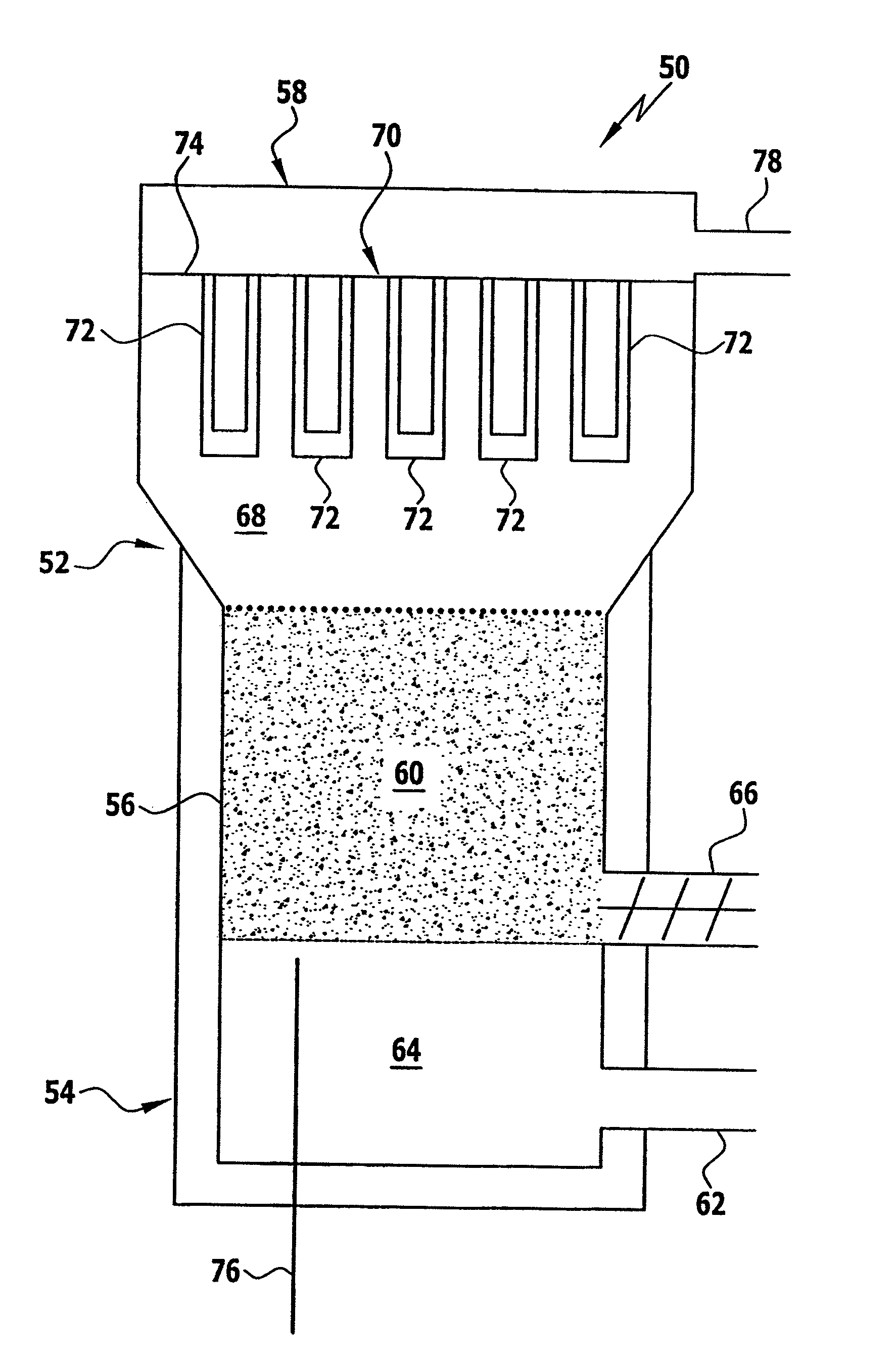
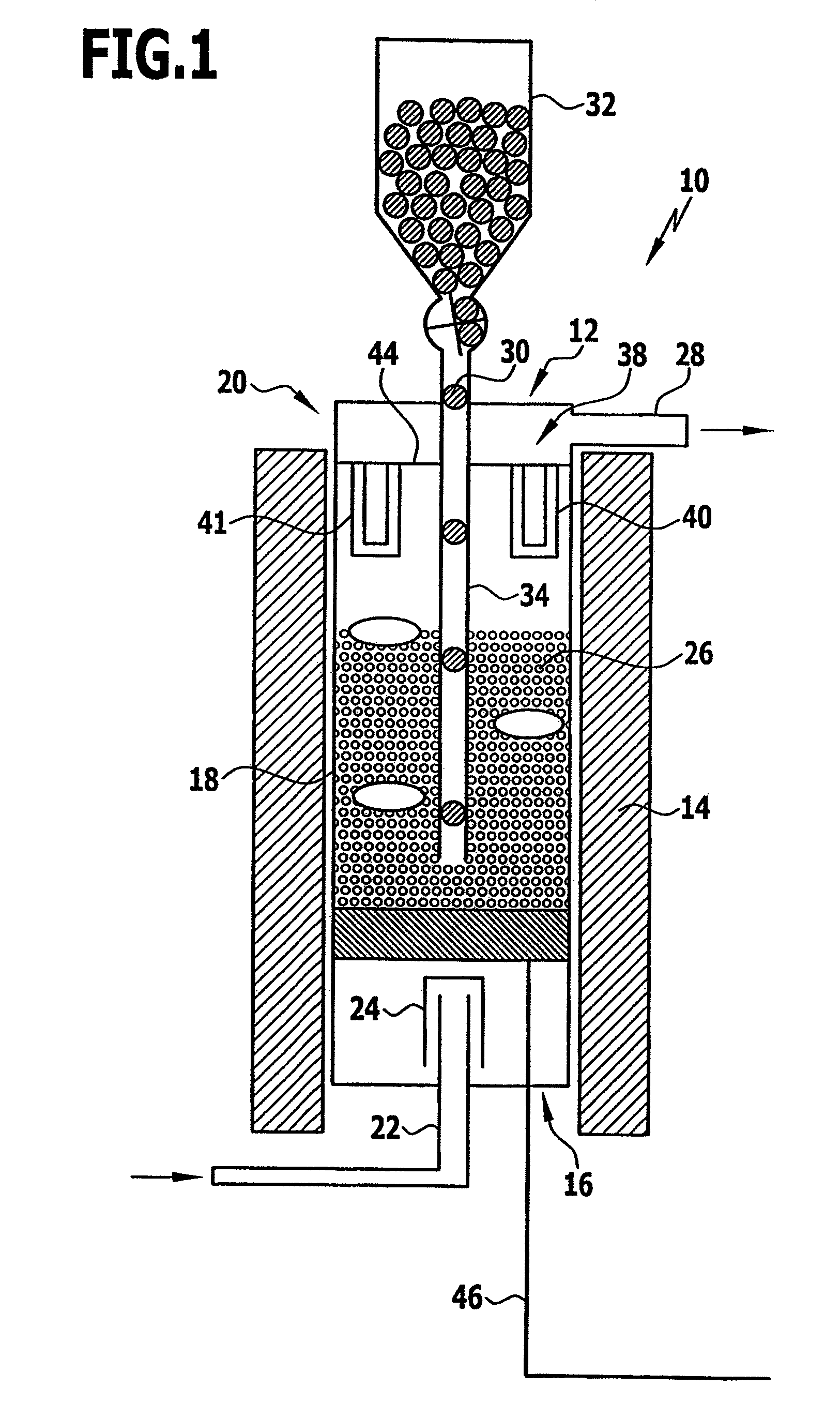
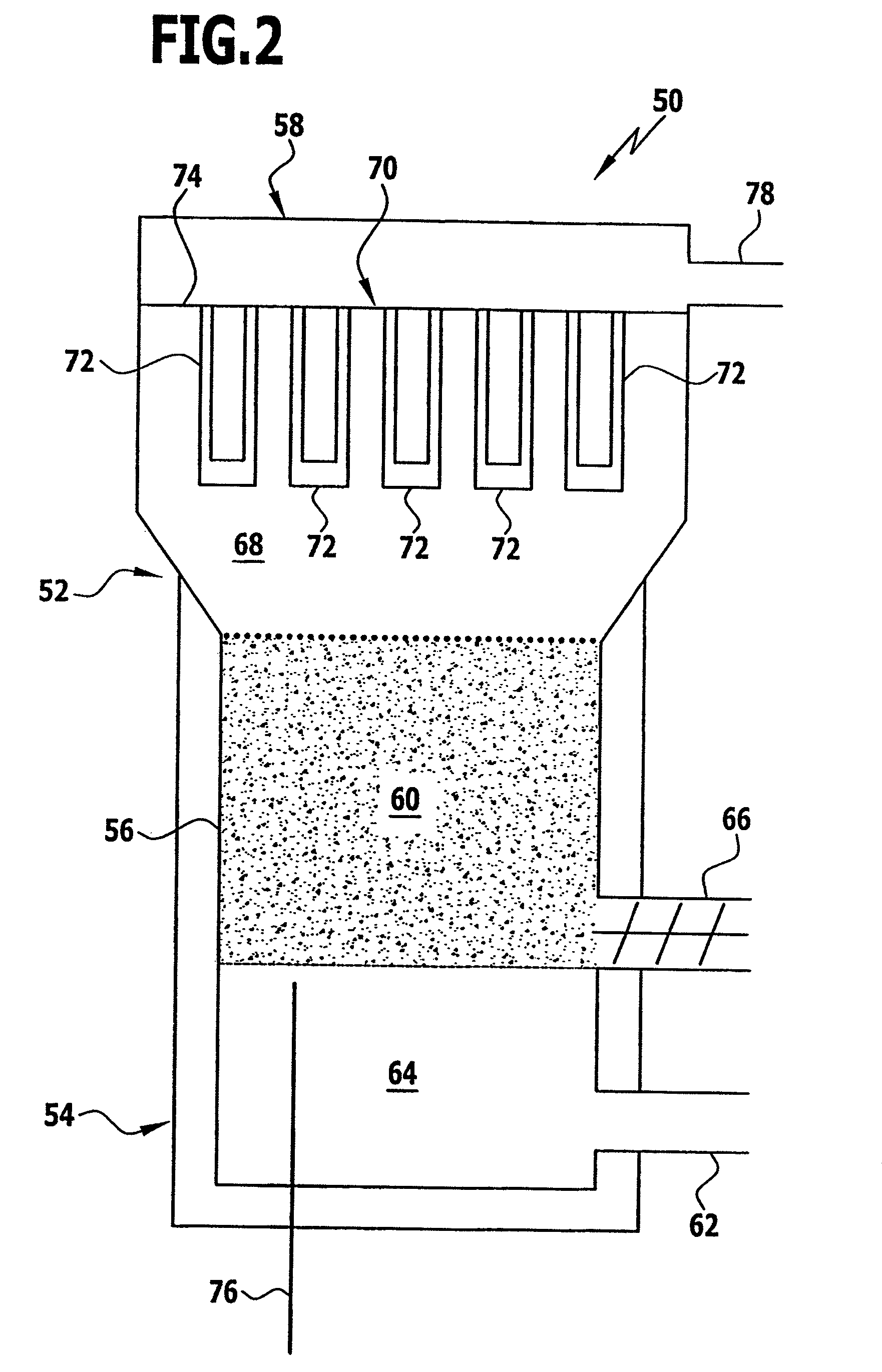
[0114]In the present Example an apparatus similar to apparatus 10 of FIG. 1 has been used. The filtering unit comprised a filter element comprising a porous SiC support element provided with a MgO—Al2O3 coating and a NiO catalyst deposited thereon. The filter element was of the dimensions 60 / 40 mm (outer / inner diameter)×368 mm (length) corresponding to an effective filtration surface of 0.06937 m2 and was accommodated in the upper end portion of a vessel, i.e., in the freeboard of a bubbling fluidized-bed gasifying reactor similar to the one shown in FIG. 1. On its upstream surface, the filter element was equipped with a membrane having an average pore size of about 10 μm.

[0115]Thus the filter element had a simpler structure as compared to the filter elements described in connection with FIGS. 3 through 5.

[0116]Almond shells were used as biomass feedstock material and olivine in particulate form was used as bed material.

[0117]The gasification process was carried out as a steam gasif...


PUM

PropertyMeasurementUnit
temperaturesaaaaaaaaaa
temperatureaaaaaaaaaa

Abstract

The present invention relates to a gasification apparatus for generating syngas from gasifiable feedstock material, said apparatus comprisinga vessel having a feedstock inlet, an inlet for a gaseous gasifying medium, an outlet for exhausted feedstock material and a syngas outlet;a gasifying reactor accommodated in said vessel and in fluid communication with said feedstock inlet, said outlet for exhausted feedstock material and said inlet for said gasifying medium of said vessel; anda filtering unit accommodated in said vessel and having an upstream side and a downstream side, said upstream side of said filtering unit being in fluid communication with said reactor and said downstream side thereof being in fluid communication with said syngas outlet.

Description

FIELD OF THE INVENTION[0001]The present invention relates to a gasification apparatus and a method for generating syngas from a gasifiable feedstock material.BACKGROUND OF THE INVENTION[0002]Gasification apparatuses and methods for generating syngas have been found convenient to convert gasifiable feedstock material into a gaseous fuel by means of a high-temperature process. As a result of rather complex thermo-chemical reactions, gasifiable feedstock, e.g., biomass, is thus transformed into permanent gases such as hydrogen, carbon monoxide, carbon dioxide and methane which usually contain organic vapours which condense under ambient conditions and are known collectively as tar and a solid residue mainly consisting of char and ash.[0003]Conventionally, the gasification process is carried out in a gasifying reactor accommodated in a vessel and the resulting crude permanent gases, in the following called crude syngas, are withdrawn from the vessel and passed through further equipment ...

Claims


Application Information

Patent Timeline
Patent Type & Authority Patents(United States)
IPC IPC(8): C01B3/36
CPCB01D46/2407C10J3/482C10J3/84C10K1/024B01J23/78C10J2200/156C10J2200/158C10J2300/0916C10J2300/0923C10J2300/0973C10J2300/1276Y02P20/145Y02P20/52
Inventor HEIDENREICH, STEFFENNACKEN, MANFREDFOSCOLO, PIER UGORAPAGNA, SERGIO
Owner PALL CORP
Why Eureka
Try Eureka