Coded aperture aided navigation and geolocation systems

a technology of geolocation and coded apertures, applied in the direction of distance measurement, image enhancement, instruments, etc., can solve the problems of less desirable passive sensors and sensors, and achieve the effects of improving the performance of the navigation system, reducing measurement covariance, and achieving greater range estimation accuracy

Inactive Publication Date: 2013-11-05
THE GOVERNMENT OF THE US SEC THE AIR FORCE
View PDF7 Cites 43 Cited by
  • Summary
  • Abstract
  • Description
  • Claims
  • Application Information

AI Technical Summary

Benefits of technology

[0013]The addition of the coded aperture improves the performance of the navigation system by both providing feature location estimates with a smaller covariance due to the addition of the range information, thereby reducing the measurement covariance. Also, a greater accuracy in the range estimates result in reduced bias in the navigation solution through reducing linearization errors of the extended Kalman filter.

Problems solved by technology

The generally higher power requirements of active sensors, such as laser radar (LIDAR), render such sensors less desirable than passive sensors.

Method used


Image

  • Coded aperture aided navigation and geolocation systems
  • Coded aperture aided navigation and geolocation systems
  • Coded aperture aided navigation and geolocation systems

Examples


Embodiment Construction

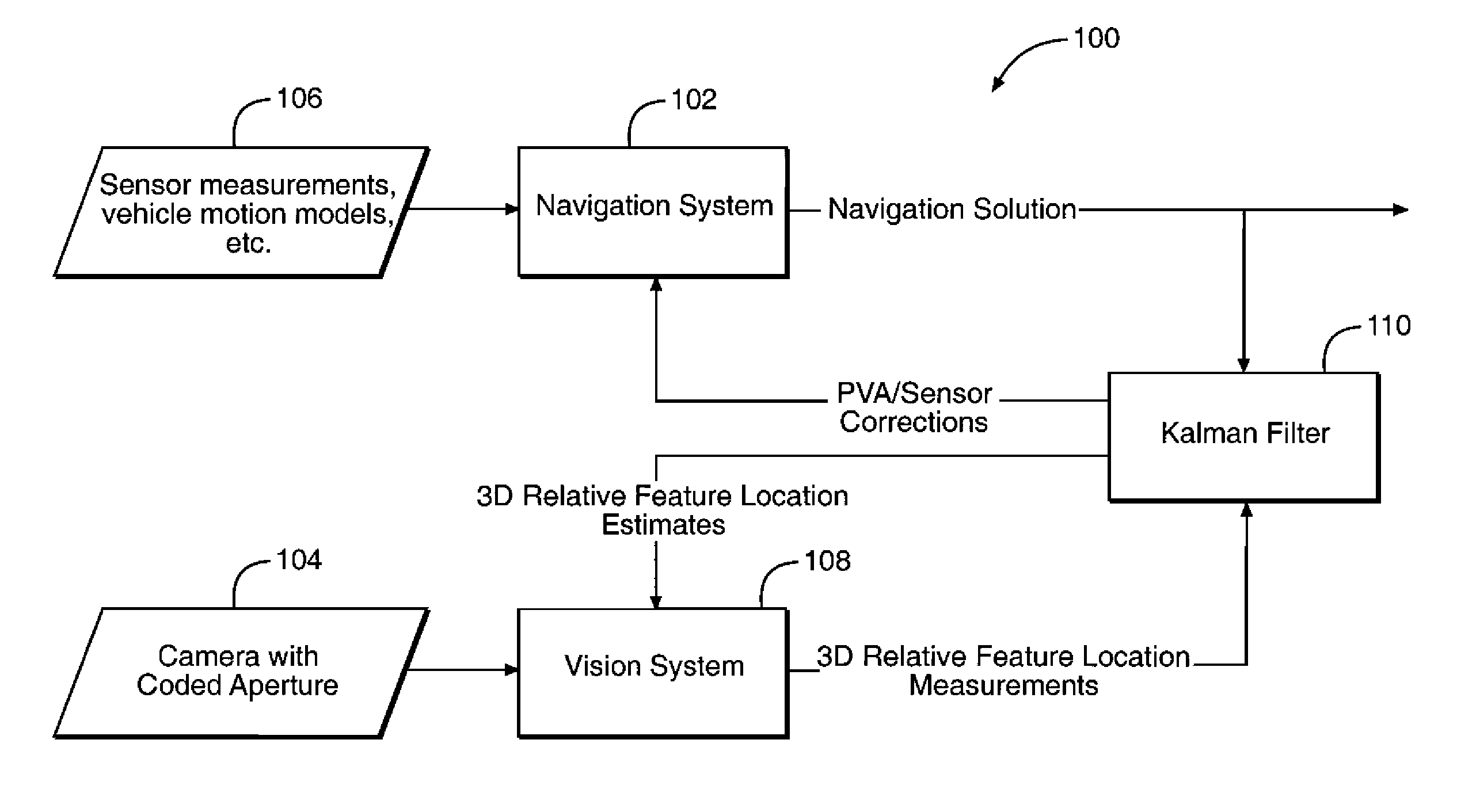
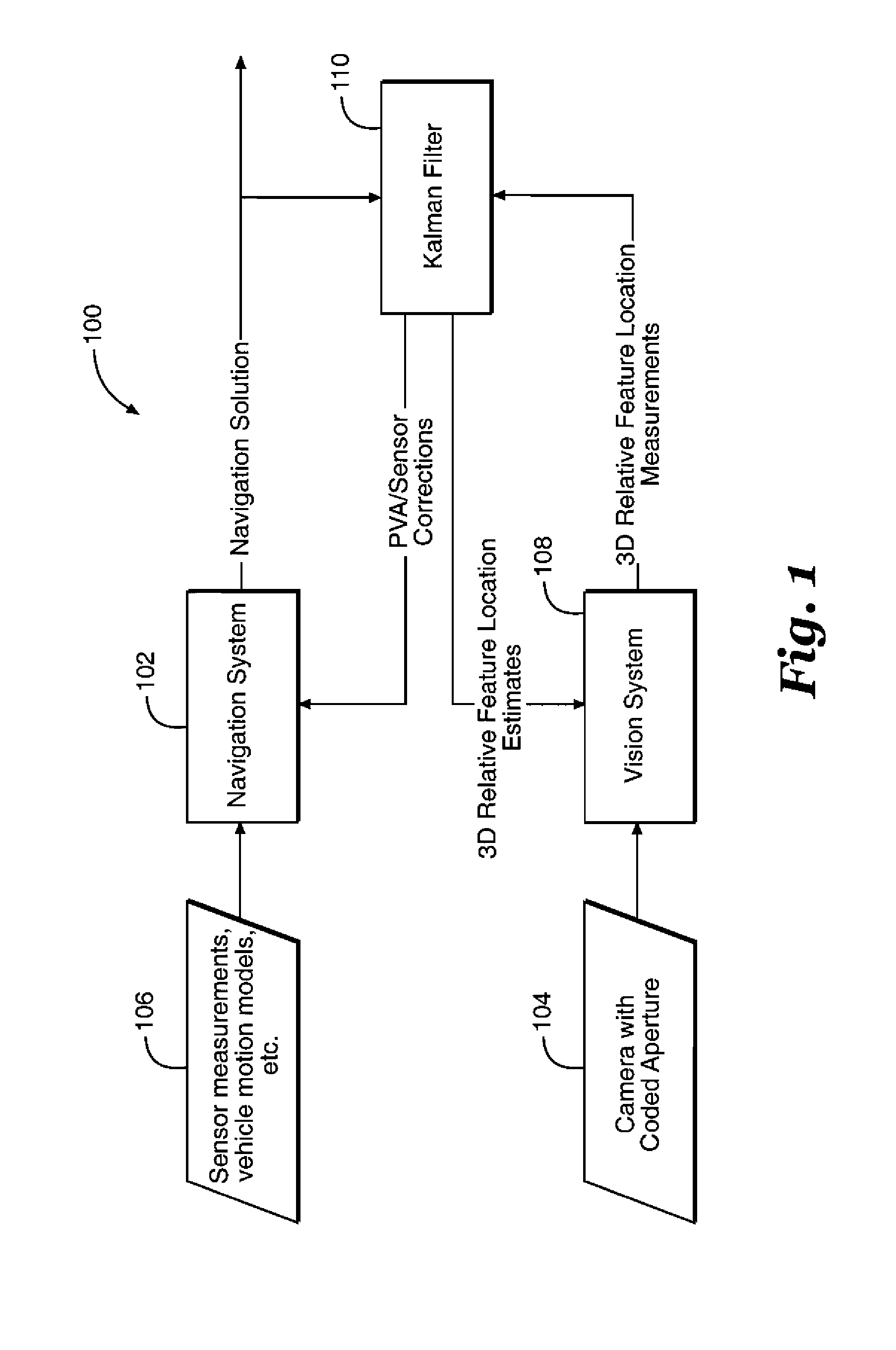
[0018]FIG. 1 illustrates a block diagram 100 of micro air vehicle including an image aided inertial navigation system 102 of the present invention. By using the position, velocity, and attitude (PVA) measurements from the INS of the micro air vehicle as the navigation solution and periodically correcting the INS based on observations from image data, a micro air vehicle can be controlled in flight by a single camera having a coded aperture 104. The camera includes a camera lens having a fixed focal length to enable the present invention to utilize the defocused portions of images to determine distance as described herein. It is preferred to select a lens having a focal length providing approximately 20 pixels of blur around a point in an image. Since many inertial navigation systems can produce PVA measurements at a much faster rate than an imaging system, the present invention uses a scheme of periodic correction of the INS by the imaging system which then allows the overall naviga...


PUM


Abstract

A micro air vehicle having a navigation system with a single camera to determine position and attitude of the vehicle using changes the direction to the observed features. The difference between the expected directions to the observed features versus the measured direction to the observed features is used to correct a navigation solution.

Description

CROSS-REFERENCE TO RELATED APPLICATION[0001]This application claims benefit of U.S. Provisional Patent Application Ser. No. 61 / 298,573, filed Jan. 27, 2010, titled “Coded Aperture Aided Navigation and Geolocation System” to Morrison et al., the disclosure of which is expressly incorporated by reference herein.RIGHTS OF THE GOVERNMENT[0002]The invention described herein may be manufactured and used by or for the Government of the United States for all governmental purposes without the payment of any royalty.BACKGROUND OF THE INVENTION[0003]Tremendous gains have been made in recent years towards achieving the goal of performing autonomous navigation of micro air vehicles (MAV), however several considerable challenges remain. Perhaps the most significant obstacle is that satellite based navigation aids such as the Global Position System (GPS) may either perform poorly or be altogether unavailable when used for indoor environments. An inertial navigation system is effective for indoor n...

Claims


Application Information

Patent Timeline
Patent Type & Authority Patents(United States)
IPC IPC(8): G01C22/00G05D1/00
CPCG01C21/165G01C21/206G06T7/0042G06T7/0069G06T2200/21G06T2207/10016G06T2207/30244G06T2207/30252G06T7/73G06T7/571G01C21/1656
Inventor MORRISON, JAMIE R.RAQUET, JOHN F.VETH, MICHAEL J.
Owner THE GOVERNMENT OF THE US SEC THE AIR FORCE
Why Eureka
Try Eureka