Exhaust gas purifying device

a technology of exhaust gas and purification device, which is applied in the direction of machine/engine, separation process, weaving, etc., can solve the problems of reducing the sealing performance or the like, forming a waste of space, so as to prevent the reduction of the sealing performance of the gas purification, the maintenance work can be easily executed, and the length of the plural sets can be shortened.

Active Publication Date: 2013-11-12
YANMAR POWER TECHNOLOGY CO LTD
View PDF26 Cites 9 Cited by
  • Summary
  • Abstract
  • Description
  • Claims
  • Application Information

AI Technical Summary

Benefits of technology

[0019]In accordance with the second aspect of the present invention, since the exhaust gas purifying device has the structure in which two kinds of the gas purifying filters are provided, the inner case internally provided with one of the gas purifying filters is overlapped by the outer case internally provided with the inner case of the other gas purifying filter, it is possible to shorten the length of the plural sets of outer cases in the exhaust gas moving direction while securing the length of a plurality of gas purifying filters in the exhaust gas moving direction. Further, since the inner case (the other of the gas purifying filters) over which the outer case laps is greatly exposed to outside on the basis of a separation (a disassembly) of each of the outer cases, an exposing range of the inner case (the other of the gas purifying filters) becomes larger, making it possible to easily execute a maintenance work such as a removal of a soot of one of the gas purifying filters.
[0020]In accordance with the third aspect of the present invention, since the exhaust gas purifying device has the structure in which the inner case support body having the ring shape is provided between the inner case and the outer case, the inner case support body is formed by the flexible material having the vibration damping function, and the inner case is supported to the outer case via the inner case support body, the vibration of the outer case is damped by the inner case support body, reducing the vibration transmitted from the outer case to the inner case, and consequently making it possible to easily prevent a reduction of a sealing performance of the gas purifying filter, and a damage or a dropout of the outer case, the inner case, or the gas purifying filter. In other words, it is possible to reduce a reduction of the sealing performance of the outer case or the inner case, and to improve a durability of the gas purifying filter. Further, for example, even in the filter structure in which an exhaust gas purifying capacity is enhanced by combining a plurality of the gas purifying filters, it is possible to easily improve a maintenance workability of the gas purifying filter.
[0021]In accordance with the fourth aspect of the present invention, since the exhaust gas purifying device includes the exhaust noise damping body for damping the exhaust noise of the exhaust gas discharged from the engine, the exhaust noise damping body arranged in the exhaust gas outlet side end portion of the outer case, it is possible to easily add an exhaust gas noise reduction function without changing the structure of the gas purifying filter, while maintaining the exhaust gas purifying function of the gas purifying filter. For example, it is possible to easily construct an exhaust gas structure in which a tail pipe is directly connected to the outer case, and an exhaust gas structure which further improves a noise reduction function of the existing silencer. Further, it is possible to easily execute a high frequency reduction countermeasure of the exhaust gas which has been hard to be executed by the gas purifying filter. For example, it is possible to easily install the exhaust noise damping body formed by a punch hole and a fiber type mat or the like.
[0022]In accordance with the fifth aspect of the present invention, since the exhaust gas purifying device has the structure in which the inlet pipe is arranged on the outer side of the outer case, the exhaust gas inlet is open to the inner case and the outer case so as to be opposed to the exhaust gas outlet side of the inlet pipe, the rectifying chamber is formed between the end face of the outer case and the end face of the gas purifying filter on the upstream side in the exhaust gas moving direction along the outer case, and the rectifying ch...

Problems solved by technology

In other words, it is necessary to enlarge a dimension of the casing in a gas moving direction of the particulate filter in comparison with a dimension necessary for installing a plurality of particulate filter, which accordingly causes a problem that a useless space is formed.
Therefore, there is a problem that a maintenance work such as a soot removal or the like cannot be easily executed.
The outer case, the inner case, the particulate filter, or the support portion thereof may be deformed and damaged by the oscillation (the deforming stress), causing a reduction of a ...

Method used


Image

  • Exhaust gas purifying device
  • Exhaust gas purifying device
  • Exhaust gas purifying device

Examples


Embodiment Construction

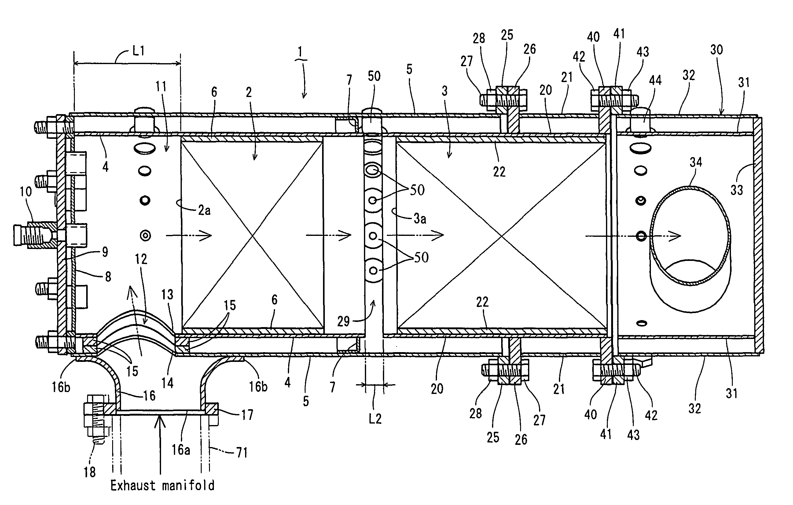
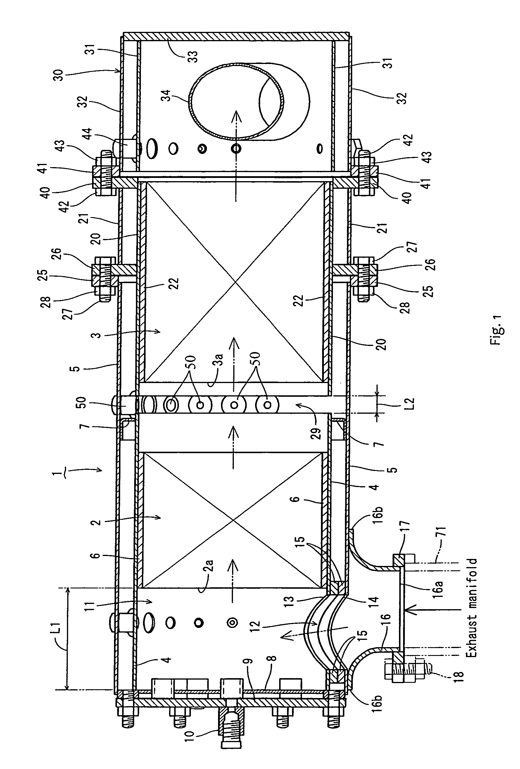
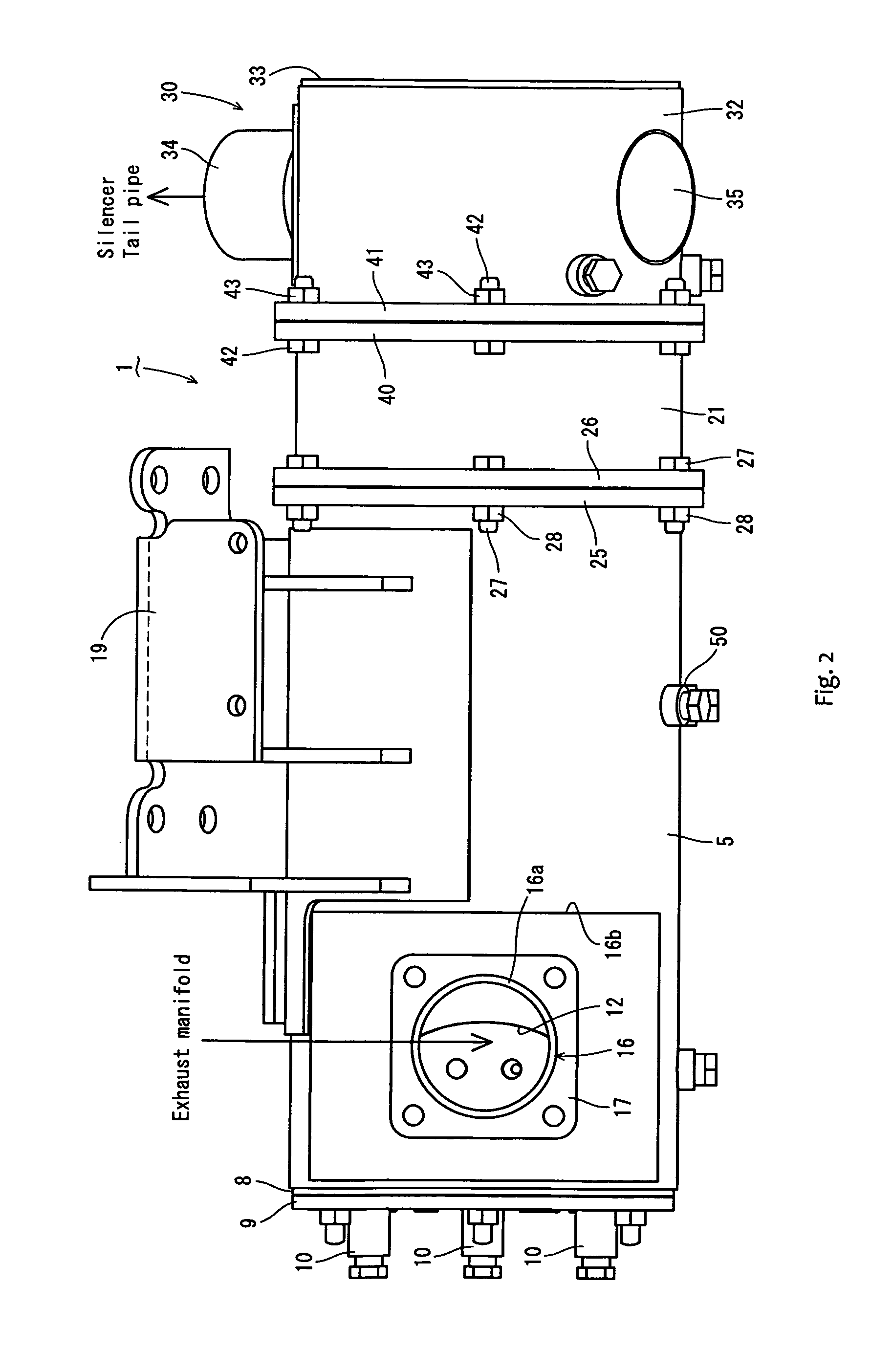
[0052]An embodiment obtained by specifying the present invention will be described below with reference to the accompanying drawings. FIG. 1 is a cross sectional view in a front view of an exhaust gas purifying device, FIG. 2 is a bottom elevational view of an outer appearance of the same, FIG. 3 is a left side elevational view as seen from an exhaust gas inflow side of the same, FIG. 4 is a right side elevational view as seen from an exhaust gas discharge side of the same, FIG. 5 is an exploded cross sectional view in a front view of FIG. 1, FIG. 6 is an enlarged cross sectional view in a front view of the exhaust gas discharge side of the same, FIG. 7 is an enlarged cross sectional view in a side elevational view of the exhaust gas discharge side of the same, FIG. 8 is an enlarged bottom elevational view of the exhaust gas inflow side of the same, and FIG. 9 is an enlarged cross sectional view in a plan view of the exhaust gas inflow side of the same. A whole structure of the exha...


PUM

PropertyMeasurementUnit
Areaaaaaaaaaaa

Abstract

Provided is an exhaust gas purifying device structured such that a gas sensor or the like can be easily arranged while an installation length of gas purifying filters can be formed compact. The exhaust gas purifying device includes the gas purifying filters for purifying an exhaust gas discharged from an engine, inner cases internally provided with the gas purifying filters, and outer cases internally provided with the inner cases. Provided are sets of the gas purifying filters, the inner cases and the outer cases, and flange bodies connecting plural sets of outer cases are offset with respect to a connection boundary position of plural sets of gas purifying filters.

Description

TECHNICAL FIELD[0001]The present invention relates to an exhaust gas purifying device mounted on a diesel engine or the like, and more particularly to an exhaust gas purifying device removing a particulate matter (soot and particulate) or a nitrogen oxide (NOx) included in an exhaust gas.BACKGROUND OF THE INVENTION[0002]Conventionally, in an exhaust gas purifying device applied to a diesel engine or the like, there has been a technique that a diesel particulate filter (or an NOx catalyst) or the like is provided in an exhaust gas discharge route of the diesel engine mounted to a traveling machine body or the like, and the exhaust gas discharged out of the diesel engine is purified by the diesel particulate filter (or the NOx catalyst) or the like (Patent Document 1, Patent Document 2, and Patent Document 3). Further, there has been known a technique in which a filter case (an inner case) is provided within a casing (an outer case), and a particulate filter is arranged within the fil...

Claims


Application Information

Patent Timeline
IPC IPC(8): B01D50/00F01N3/021F01N3/10
CPCF01N1/10F01N3/0335F01N3/035F01N3/2875F01N13/1855F01N3/0211F01N13/0097F01N13/0093F01N2450/30F01N2590/08Y10T428/24678Y10T428/249922B01D53/94F01N3/02F01N3/24F01N3/28
Inventor MITSUDA, MASATAKA
Owner YANMAR POWER TECHNOLOGY CO LTD
Why Eureka
Try Eureka