
Method for preparing sintered annular nuclear fuel pellet

a technology of nuclear fuel pellet and annular nucleus, which is applied in the direction of nuclear elements, manufacturing tools, greenhouse gas reduction, etc., can solve the problems of affecting the performance of commercial nuclear fuel rod in terms of temperature and heat flux, affecting the safety of nuclear fuel rods, and degrading the heat transmission. to potentially damage the nuclear fuel rod

Active Publication Date: 2013-11-19
KOREA HYDRO & NUCLEAR POWER CO LTD +1
View PDF19 Cites 1 Cited by
  • Summary
  • Abstract
  • Description
  • Claims
  • Application Information

AI Technical Summary

Benefits of technology

[0027]An aspect of the present invention provides a method for fabricating a sintered annular nuclear fuel pellet capable of maintaining a uniform value of an inner diameter of a sintered annular nuclear fuel pellet and maintaining a low level (±13 μm, a current specification of a dimension tolerance of a commercial nuclear fuel pellet, or lower) of inner diameter tolerance with respect to the length (in the direction of a central axis) of the pellet, without performing a disadvantageous grinding process.
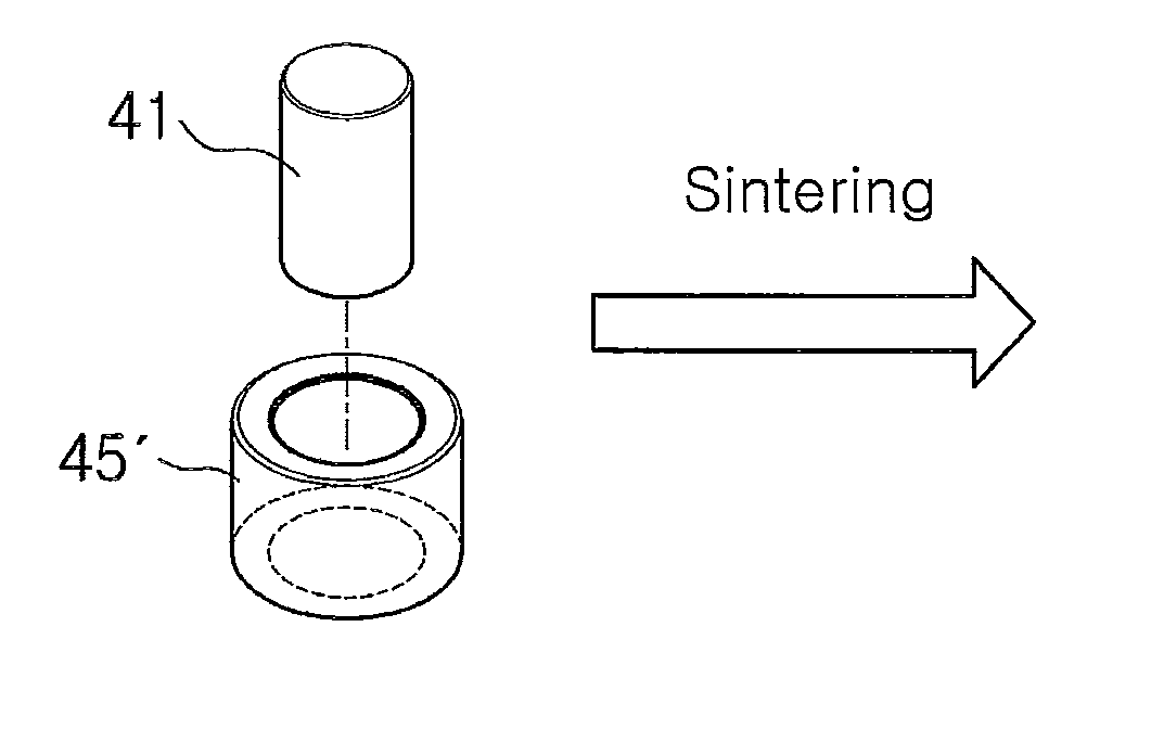
[0028]According to an aspect of the present invention, there is provided a method for fabricating a sintered annular nuclear fuel pellet, including: pressing nuclear fuel powder or granule, an oxide of a fissile element (M), to fabricate an annular nuclear fuel green body; inserting a rod-like shaped structure into the annular nuclear fuel green body; sintering the rod-like shaped structure-inserted annular nuclear fuel green body in the slight oxidizing gas atmosphere such that the oxide of the fissile element has a balanced O / M ratio (oxygen / fissile element) higher than a desired O / M ratio of a final sintered annular nuclear fuel pellet, while being maintained in a cubic phase; reducing the sintered annular nuclear fuel pellet in a reductive gas atmosphere so as to have the desired O / M ratio in the state that the rod-like shaped structure is inserted; and separating the rod-like shaped structure from the reduced sintered annular nuclear fuel pellet.

Problems solved by technology

Such a commercial nuclear fuel rod is limited in its performance in terms of temperature and heat flux.
The pellet remaining at a high temperature results in an encroachment of a margin for safety in the occurrence of various design basis nuclear reactor accidents.
The occurrence of the departure of nucleate boiling leads to a formation of an air bubble curtain on the surface of the cladding tube, severely degrading a heat transmission to potentially damage the nuclear fuel rod.
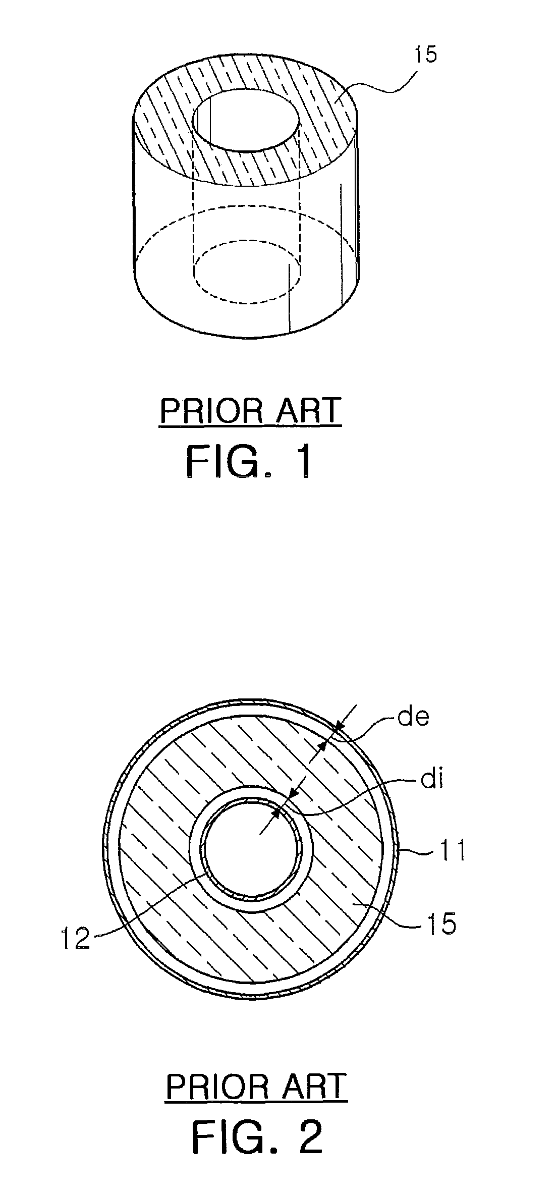
The amount of generated heat transferred via either of the inner and outer cladding tubes has a connection with the thermal resistance of both directions, so a larger amount of heat is distributed to the cladding tube having a smaller thermal resistance, causing a problem in that the heat flux of one cladding tube becomes higher than that of the other cladding tube.
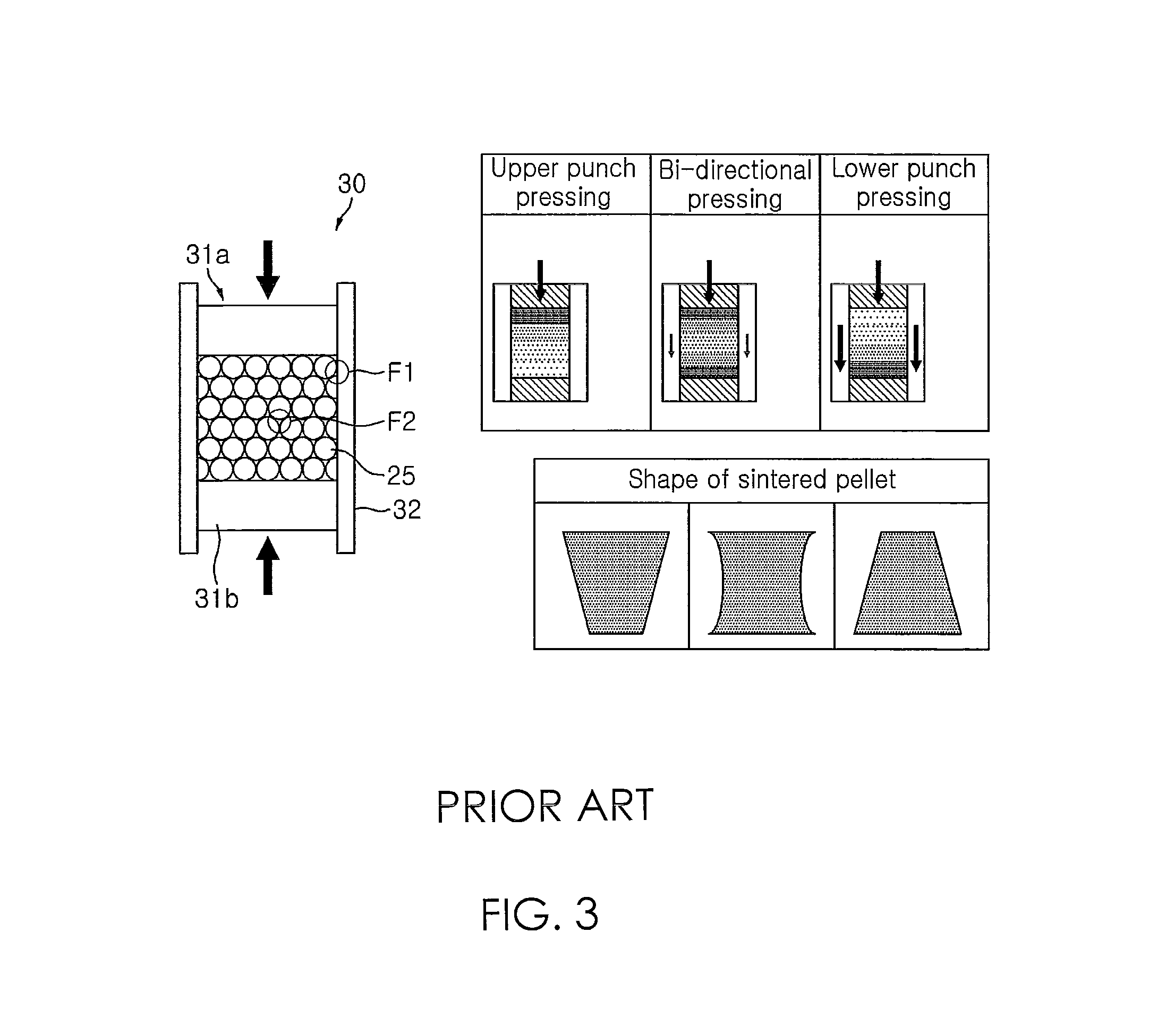
The difference in the green density in the green body causes a difference in the sintering shrinkage of each part of the green body during sintering, triggering deformation and even cracking in a worst case scenario.
In this respect, however, because the inner diameter distribution of the sintered annular pellet is different for each sintered pellet, in case of the diamond wheel grinding, the sintered annular pellets must be held one by one and ground, unlike centerless grinding, resulting in degradation of productivity.
However, in case of sandblasting, uranium and sand are mixed with the grinding residues, making it difficult to recycle the costly uranium content.
Thus, a problem arises in separating the uranium from the grinding residues and controlling the impurity contents.

Method used


Image

  • Method for preparing sintered annular nuclear fuel pellet
  • Method for preparing sintered annular nuclear fuel pellet
  • Method for preparing sintered annular nuclear fuel pellet

Examples


embodiment

[0072]IDR-UO2 powder was pre-compacted under 0.1 ton / cm2. Pre-compacted lump of UO2 powder was crushed and allowed to pass through a 50-mesh sieve to fabricate granules. 0.3 wt % of zinc state was added as a lubricant to the fabricated granules, which were then mixed in a tubular mixer for 30 minutes.

[0073]The thusly mixed granules were charged (i.e., loaded) in a double acting uniaxial press and pressed with a pressure of about 4 ton / cm2 to fabricate an annular green body. The inner and outer diameters of the annular green body were measured at every interval of 1 mm along the length of the green body by using a contact type three-dimensional measurement machine. The density of the annular green body was an about 54 percent of the theoretical density.

[0074]The annular green body with an yttria-stabilized ZrO2 rod having an outer diameter of 10.156 mm inserted therein was sintered in a carbon dioxide atmosphere for four hours at a temperature of 1,250 degrees Celsius, and then reduc...


PUM

PropertyMeasurementUnit
temperatureaaaaaaaaaa
lengthaaaaaaaaaa

Abstract

A method for fabricating a sintered annular nuclear fuel pellet includes molding nuclear fuel powder or granule, an oxide of a fissile element (M), to fabricate an annular nuclear fuel green body. A rod-like shaped structure is inserted into the annular nuclear fuel green body and sintered in a slight oxidizing gas atmosphere such that the oxide of the fissile element has a balanced O / M ratio higher than a desired O / M ratio (oxygen / fissile element) of a final sintered annular nuclear fuel pellet, while being maintained in a cubic phase. The sintered annular nuclear fuel pellet is then reduced in a reductive gas atmosphere so as to have the desired O / M ratio in the state that the rod-like shaped structure is inserted.

Description

CROSS-REFERENCE TO RELATED APPLICATIONS[0001]This application claims the priority of Korean Patent Application No. 10-2009-0083123 filed on Sep. 3, 2009, in the Korean Intellectual Property Office, the disclosure of which is incorporated herein by reference.BACKGROUND OF THE INVENTION[0002]1. Field of the Invention[0003]The present invention relates to a sintered annular nuclear fuel pellet and, more particularly, to a method for fabricating a sintered annular nuclear fuel pellet without performing an inner side grinding processing so that the sintered annular nuclear fuel pellet can be used for a dual-cooling nuclear fuel rod that heat transfer simultaneously occurs at the inner and the outer claddings.[0004]2. Description of the Related Art[0005]In general, a uranium dioxide (UO2) pellet is the most commonly used nuclear fuel of a commercial reactor. A UO2 pellet contains a certain amount (e.g., 1 wt % to 5 wt %) of U235 and, while it is in use in a nuclear reactor, U235 of the UO...

Claims


Application Information

Patent Timeline
Patent Type & Authority Patents(United States)
IPC IPC(8): G21C21/00B28B21/00B28B3/00C04B33/32
CPCG21C21/02Y02E30/30G21C3/62
Inventor RHEE, YOUNG-WOOKIM, DONG-JOOSONG, KUN-WOOKIM, JONG-HUNKIM, KEON-SIKYANG, JAE-HOKANG, KI-WON
Owner KOREA HYDRO & NUCLEAR POWER CO LTD
Learn More