Angle detection apparatus and position detection apparatus
a detection apparatus and position technology, applied in special purpose recording/indication apparatus, measurement devices, instruments, etc., can solve the problems of inability to measure the rotation angle or movement with high accuracy, unstable signal, etc., to improve the output linearity of magnetic sensors, limited rotation angle or position range, and high accuracy
- Summary
- Abstract
- Description
- Claims
- Application Information
AI Technical Summary
Benefits of technology
Problems solved by technology
Method used
Image
Examples
reference example 1
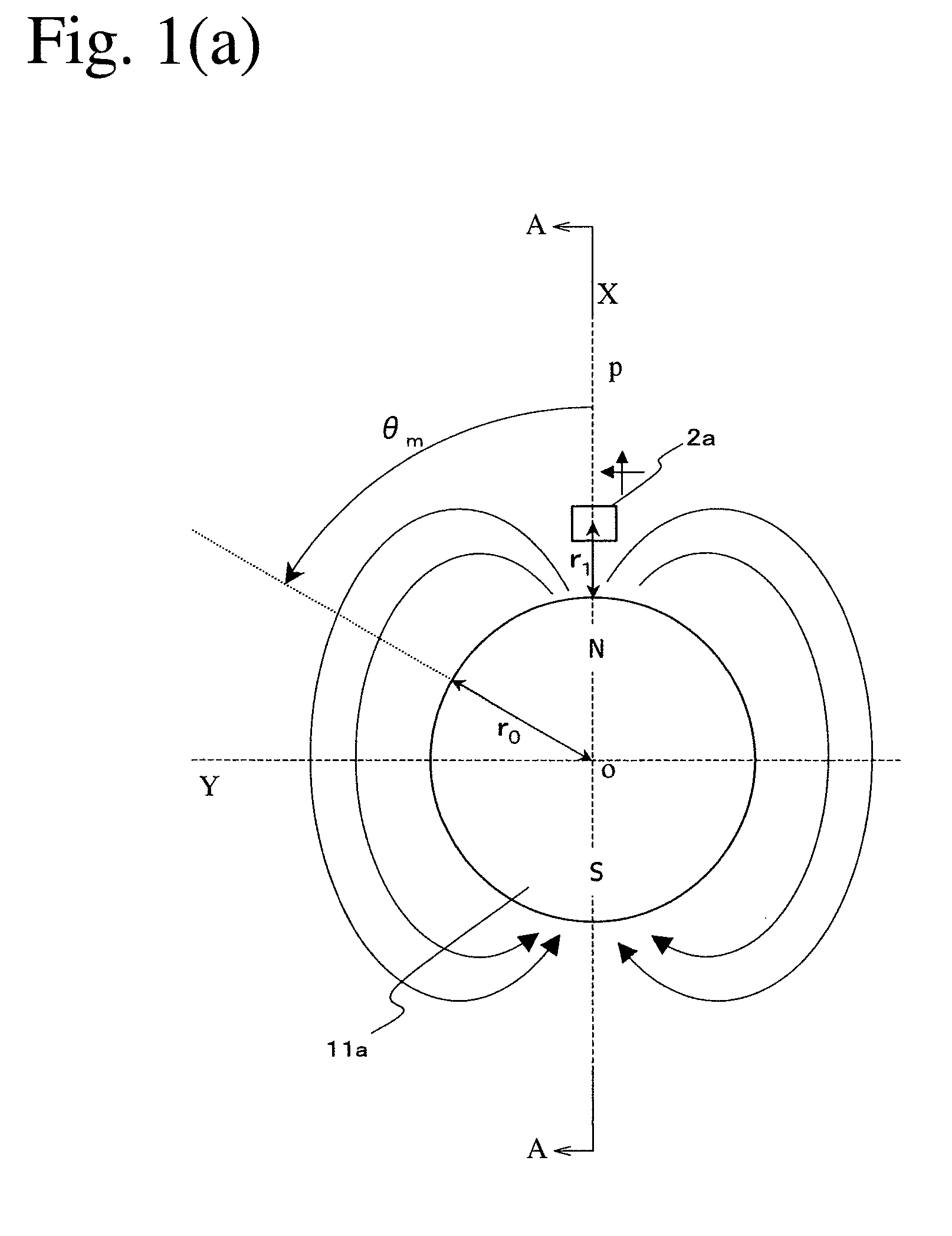
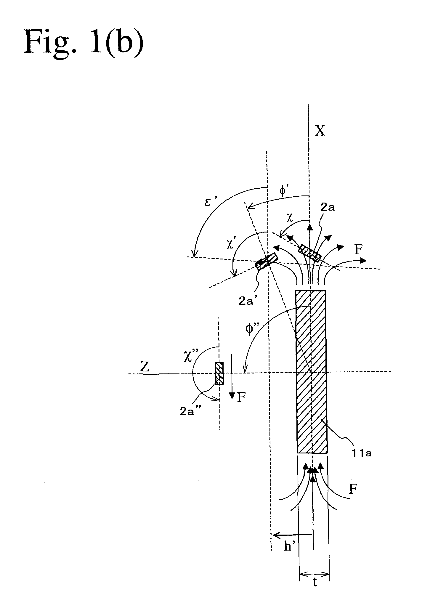
[0104]As shown in FIGS. 3(a) and 3(b), in a coordinate system (X, Y, Z) whose origin is a center O of the permanent magnet 11a, the magnetic sensor 2a shown in FIGS. 2(a)-2(c), which has a structure having bridge-connected spin-valve, giant-magnetoresistive devices, is arranged near a periphery (X, 0, 0) of the permanent magnet 11a. In the magnetic sensor 2a, the magnetosensitive plane is perpendicular to the rotating shaft of the permanent magnet 11a, and the magnetization directions of the pinned layers are in parallel to the Y axis. Magnetic flux components BX, BY, BZ in the X, Y and Z directions generated when the permanent magnet 11a rotates by an angle θm are expressed by the formulae (1).
[0105]BX=m4πR3cosθm(2cos2ϕ-sin2ϕ)BY=-m4πR3sinθmBZ=m4πR3cosθm(3cosϕ·sinϕ),(1)
wherein m represents a magnetic moment approximating the permanent magnet 11a, θm represents the rotation angle of the permanent magnet 11a, and φ represents an angle between a line c...
reference example 2
[0115]Reference Example 1 has shown a two-pole magnet providing an output having a period of an electric angle per a period of a mechanical angle, but it is advantageous to use a multi-pole magnet for detecting a small angle with high accuracy. FIGS. 8(a) and 8(b) show the angle detection apparatus of Reference Example 2. This angle detection apparatus comprises a magnet rotor comprising a 16-pole ring magnet 11b generating a polar-anisotropic magnetic field from the peripheral surface, and a shaft 13b fixed to a penetrating hole of the ring magnet 11b; and a magnetic sensor 2a arranged at a position separate from the peripheral surface of the ring magnet 11b. The radius r0 of the ring magnet 11b was 20 mm, the distance r1 from the peripheral surface of the ring magnet 11b to a center of the magnetic sensor 2a was 4 mm, the inner diameter r2 of the hole of the ring magnet 11b was 15 mm, and the thickness t of the ring magnet 11b in the Z direction (rotation axis direction of the mag...
reference example 3
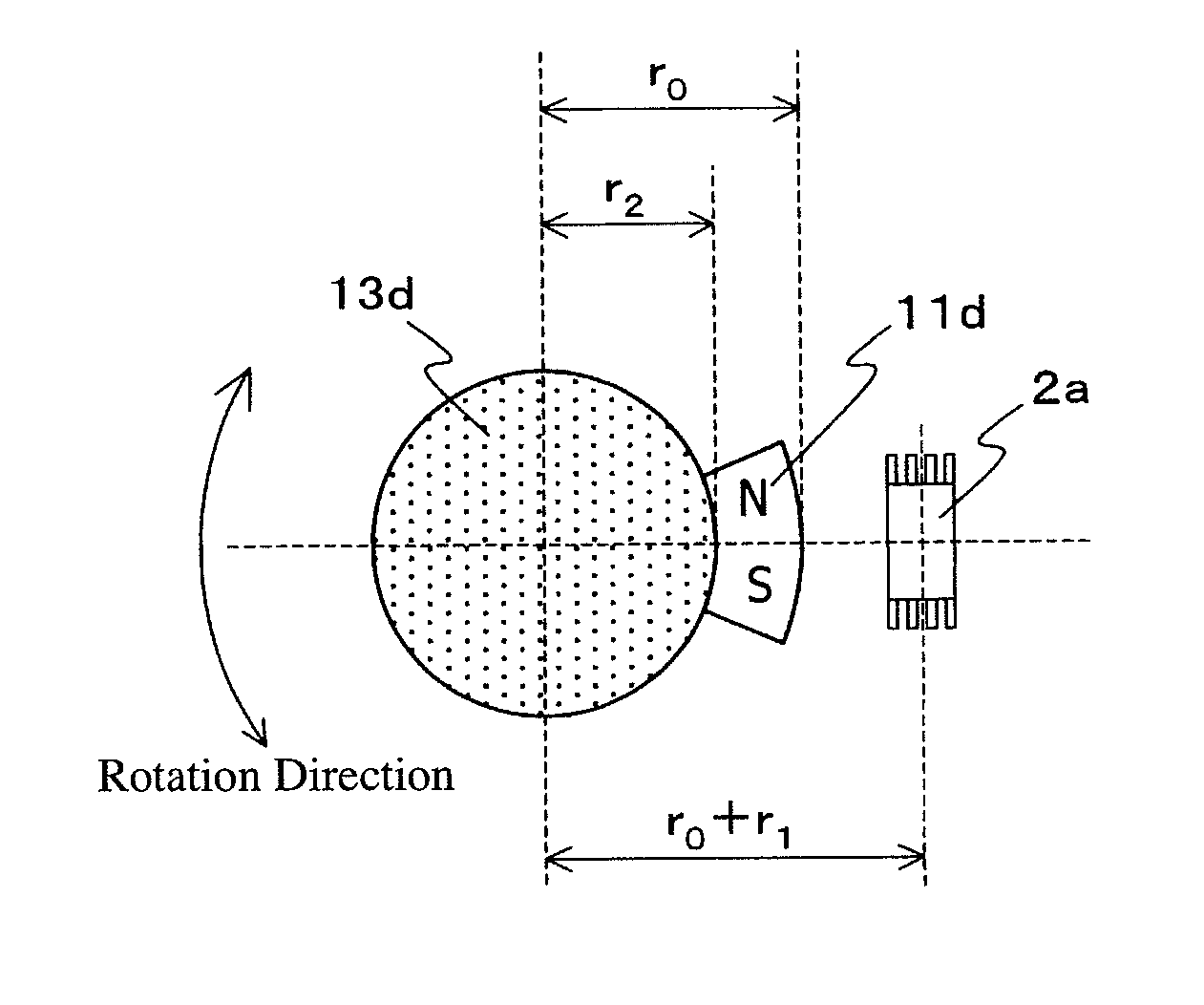
[0117]FIGS. 10(a) and 10(b) show an angle detection apparatus comprising an 8-pole ring magnet 11b′ in Reference Example 3. r0=16 mm, r1=4 mm, r2=10 mm, and t=8 mm. Because K0 was 1.3, neither inclination nor axial displacement were conducted [h=0, and χ=0 in FIG. 5(b)]. As shown in FIG. 11(a), the magnetic sensor 2a output four periods of signals in response to a period of the rotation of the multi-pole ring magnet 11b′, which corresponded to the number of magnetic poles in the magnet; one of them was a substantially triangular wave. As shown in FIG. 11(b), evaluation using one period of this signal revealed that the angle detection error was within ±0.2° in a range of ±15°.
PUM
 Abstract
Description
Claims
Application Information
 - R&D
- Intellectual Property
- Life Sciences
- Materials
- Tech Scout
- Unparalleled Data Quality
- Higher Quality Content
- 60% Fewer Hallucinations
Browse by: Latest US Patents, China's latest patents, Technical Efficacy Thesaurus, Application Domain, Technology Topic, Popular Technical Reports.
© 2025 PatSnap. All rights reserved.Legal|Privacy policy|Modern Slavery Act Transparency Statement|Sitemap|About US| Contact US: help@patsnap.com


