

Tunable multiple laser pulse scanning microscope and method of operating the same
a scanning microscope and laser pulse technology, applied in the field of tunable multiple laser pulse scanning microscope and method of operation, can solve problems such as non-optimal imaging
Active Publication Date: 2013-12-17
LEICA MICROSYSTEMS CMS GMBH
View PDF5 Cites 8 Cited by
- Summary
- Abstract
- Description
- Claims
- Application Information
AI Technical Summary
Benefits of technology
The patent describes a device that can detect the time delay between laser pulses and adjust it to control the movement of a delay stage, resulting in a different time delay and another feedback detection. This feedback control allows for a closed loop control of the delay stage. The device uses TPA detectors, which are cost-effective and robust, and are particularly suitable for ultrafast laser applications. The device also includes a beam splitter to extract a part of the laser beam for delay detection. The first and second pulsed laser light sources are designed to emit prechirped laser beams or may comprise a pump laser and an optical parametric oscillator for converting the pump laser light into the first and second laser pulses.
Problems solved by technology
Tuning at least one of the wavelengths results in a change of the temporal delay between the pulses and therefore may result in non-optimal imaging if the resulting time delay is non-optimal.
Method used
View moreImage
Smart ImageViewing Examples

Examples
first embodiment
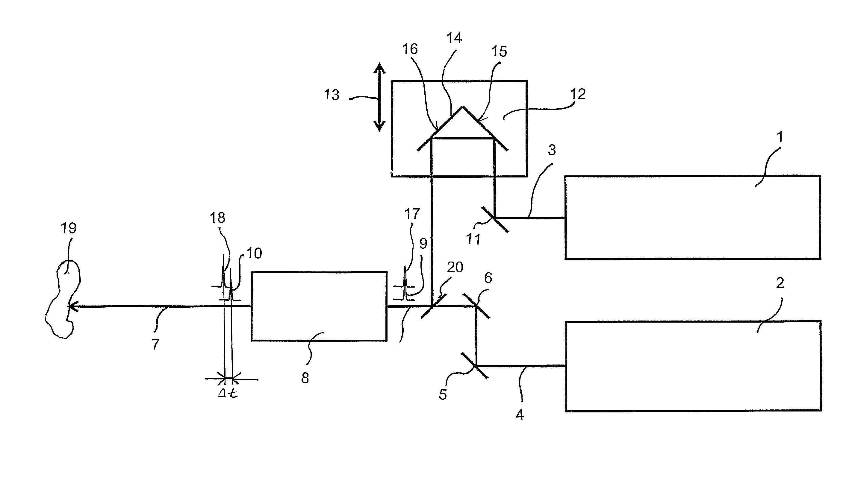
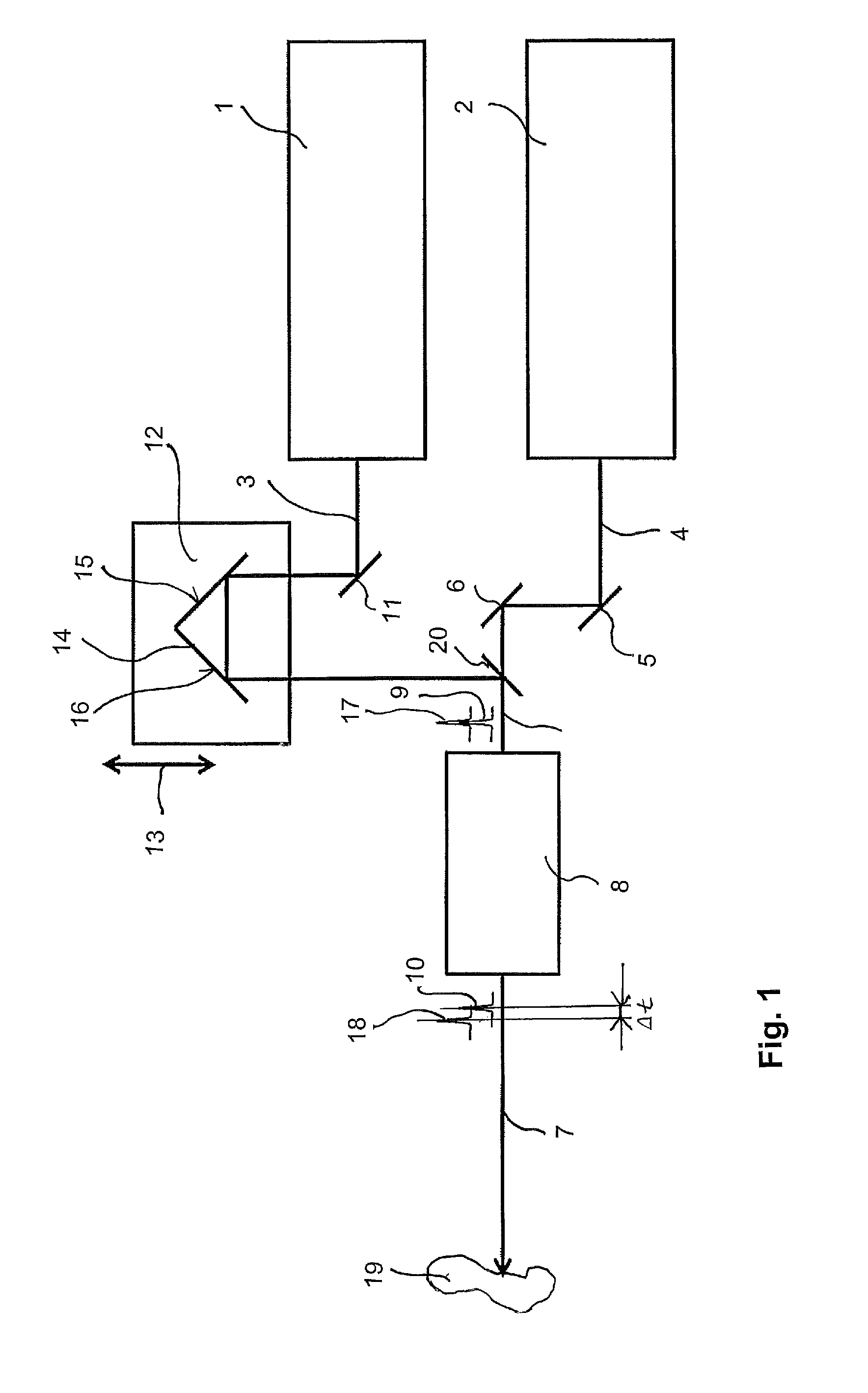
[0016]FIG. 1 shows schematically the invention applying a manual adjustment of the delay stage.
second embodiment
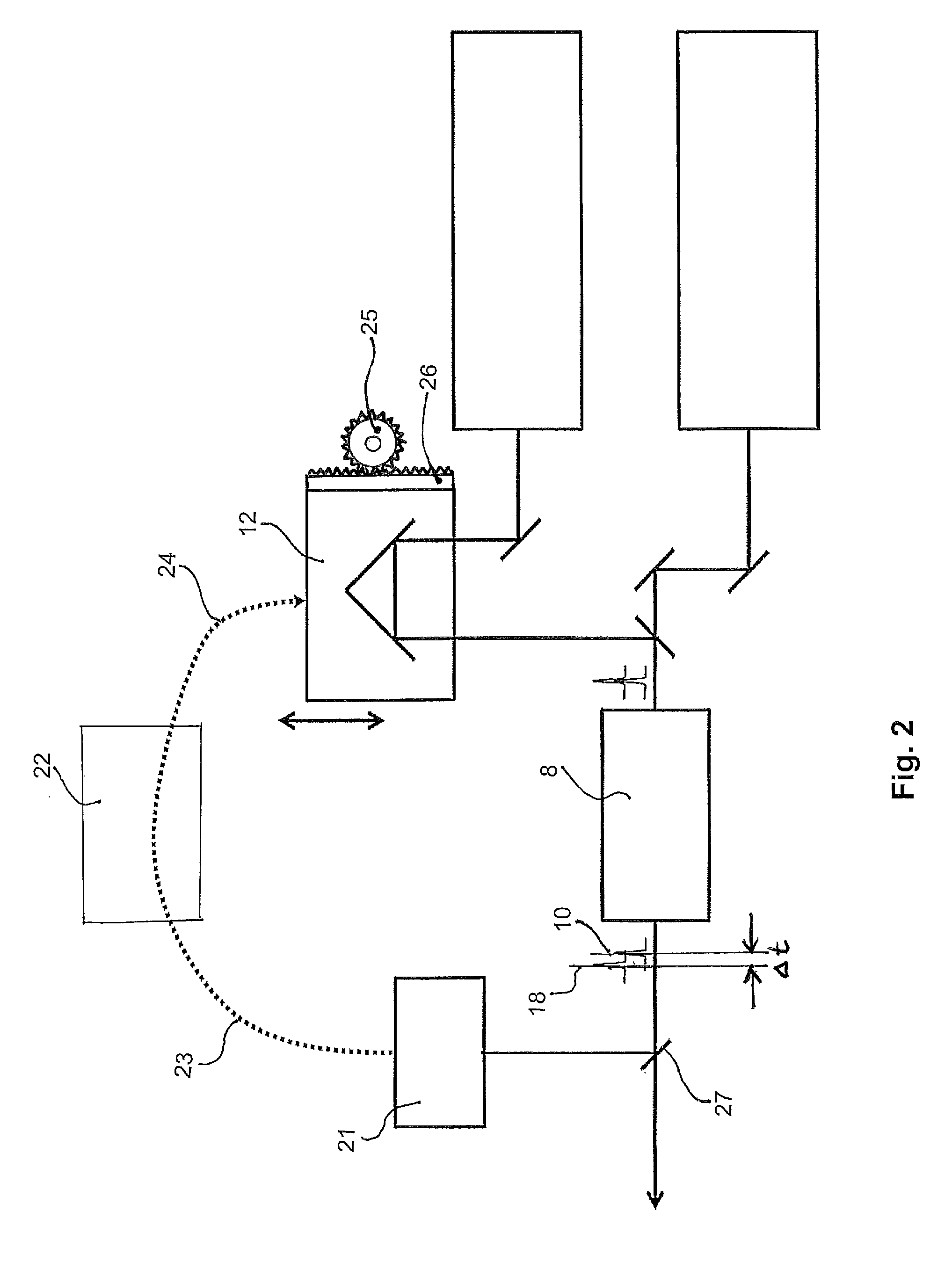
[0017]FIG. 2 shows schematically the invention applying a controlled adjustment of the delay stage.
third embodiment
[0018]FIG. 3 shows schematically the invention applying a controlled adjustment of the delay stage and comprising only one single laser source with two output wavelengths.
Login to View More PUM
| Property | Measurement | Unit |
|---|---|---|
| degree angle | aaaaa | aaaaa |
| angle | aaaaa | aaaaa |
| multiple laser pulse scanning microscope | aaaaa | aaaaa |
Abstract
A tunable multiple laser pulse scanning microscope and a method of operating the same is described, applying two pulsed laser beams with distinct wavelengths incident on a scanning spot of a sample to be imaged simultaneously or at a specific time delay. The microscope comprises at least two pulsed laser light sources emitting laser light of distinct wavelengths, an acousto-optic tunable filter (AOTF) for tuning at least one of the laser pulses, a delay stage provided upstream of the AOTF, and an actuator for moving delay stage depending on the time delay. As a result, the wavelength of at least one type of pulses is tuned, and the delay between at least two pulses of distinct wavelengths is adjusted.
Description
BACKGROUND OF THE INVENTION[0001]Microscopes applying pulsed laser beams are well-known in the art, particularly, confocal microscopes using two or more pulsed laser beams of distinct wavelengths. The two or more laser pulses are temporarily and spatially synchronized and are of different wavelengths. The laser pulses have to arrive at a particular scanning spot on a sample to be imaged either simultaneously or with a specific time delay between the laser pulses of different wavelengths, depending on the particular type of microscope. Examples for microscopes applying two different laser pulses are for instance a coherent anti-Stokes Raman scattering (CARS) microscope, a stimulated Raman scattering (SRS) microscope, a Raman-induced Kerr-effect scattering (RIKES) microscope, a sum-frequency generation (SFG) microscope, and a stimulated emission depletion (STED) microscope. An example for a microscope applying three distinct wavelengths that are incident on the sample with clearly pre...
Claims
Login to View More Application Information
Patent Timeline
 Patent Type & AuthorityPatents(United States)
IPC IPC(8): G02F1/11
CPCG02B21/0032G02B21/0076
InventorKRISHNAMACHARI, VISHNU VARDHANHAY, WILLIAM C.
OwnerLEICA MICROSYSTEMS CMS GMBH