Measurement device and a system and method for using the same

a measurement device and a technology of a measurement device, applied in the direction of mechanical measuring arrangements, using mechanical means, instruments, etc., can solve the problems of the depth measurement device of likins, the deformation or failure of the support rod, and the inability to meet the requirements of the installation process, so as to reduce the variables, improve the accuracy of the resulting system, and reduce the difficulty of use.

Active Publication Date: 2013-12-17
PILE DYNAMICS
View PDF10 Cites 2 Cited by
  • Summary
  • Abstract
  • Description
  • Claims
  • Application Information

AI Technical Summary

Benefits of technology

[0014]More particularly, the system according to the invention of this application can be fixedly mounted directly to the gearbox or hammer cage and includes a roller wheel that is forced against the rig which can include being forced against one of the leads of the support tower. The wheel or roller, which is forced against one or more leads, is joined to an encoder that can measure the rotations of the wheel to determine the travel of the cage or gearbox along the tower. This data can be used to accurately measure the depth of a driven pile, an auger, or any other installation system.
[0030]In other embodiments, a first and a second encoder assembly can be joined to the load box (or other structural component of the rig), which can be used to further improve the accuracy of the system. In this respect, by including two encoder assemblies, which are monitoring the same data, this parallel data collection can be compared to one another to better ensure that the data is correct. Further, if an abnormality is detected by the comparison of the data of the two encoder assemblies, this abnormality can be more effectively handled by having this redundant system. Thus, the data of the two sensors can either be averaged and / or compared relative to one another to eliminate abnormalities of either individual sensor.
[0032]In yet other embodiments of the invention of this application, the encoder assembly can be mounted such that it engages pulley or the roller at the top of the boom. While this mounting arrangement does not eliminate all of the variables associated with the wire, its separation from the wire arrangement and measurement based on the rotation of the top pulley greatly reduces the variables and reduces the difficulties associated with mounting the system and operating system. Further, this mounting arrangement does not require permanent alteration of the rig or welding to the rig. As with the systems described above, the sensor used on this pulley can also be a wired system or a wireless system without detracting from the invention of this application.
[0033]In yet further embodiments of this application, the encoder assembly used to monitor the rotation of this pulley. Further, this can be used in combination with one or more sensors mounted directly to the load box. Again, this can be used for error detection to further improve the accuracy of the resulting system. In addition, in view of the simplicity and low cost associated with the encoder assembly of this application, a plurality of encoder assemblies can be used cost effectively for this data acquisition.

Problems solved by technology

However, while Likins has been found to be a very effective system in the field, applicant has found that the depth measurement device of Likins has its limitations which for years went unresolved.
While the linear bearing arrangement is effective in handling the lateral movement of the wire, it is not effective in handling the changes in load in the direction of line 56 wherein it has been found that the support rod, that is used to support the linear bearing, often deforms or fails in use.
In either case, this condition adversely affects the accuracy of the depth sensor and the failure of the system in the field can cause downtime for the pile installation process.
In addition, in that many rigs are not owned by the operator, it is often difficult or impossible to convince the rig operator to weld a support bar to the rig, which is necessary to operate this type of sensing system.
These rigs can cost hundreds of thousands of dollars, if not millions of dollars, wherein the owners of the rig are often hesitant to allow the types of modifications to the boom structure of the rig which are necessary to support this sensing system.
Even if the owner of the rig can be convinced to weld the necessary fixed bar to the boom, the sensing device shown in Likins has been found to have issues with accuracy for several reasons.
It is difficult to account for the amount of wrap about this encoder wheel wherein the system inherently produces some level of error.
As can be appreciated, it is difficult to account for this ever-changing angle, which is especially true in that each rig can have a different angle and / or a different angle change.
As a result, it has been found that this system works adequately for short piles; however, the system becomes less and less accurate as the pile length increases.
Yet another problem found with the depth measurement system disclosed in the prior art is that the data produced by the system can be corrupted if the line is allowed to go slack.
A slack condition in this line affects this constant and can produce error.
Moreover, if this slack condition is not noticed, the error in the data may not be known, which would result in a less accurate data set for the pile installation period.
Depending on the frequency of the slack condition, and the other factors discussed above, the resulting data could be corrupted enough to prevent its use in evaluating the structural integrity of the installed pile.
However, this device was found to have its own problems, which prevented its effective use in the field.
In this respect, the system is heavy and expensive, weighing over 200 pounds, and produces yet another wire on the rig, which must be managed.
As is known in the art, the installation process of a pile (whether it is a driven pile or an auger-cast pile), can be harsh and have negative impacts on sensing systems and wire structures.
It has been found, that this real system can often get tangled and in the way of other structures of the rig wherein its effectiveness has been found to be limited.

Method used


Image

  • Measurement device and a system and method for using the same
  • Measurement device and a system and method for using the same
  • Measurement device and a system and method for using the same

Examples


Embodiment Construction

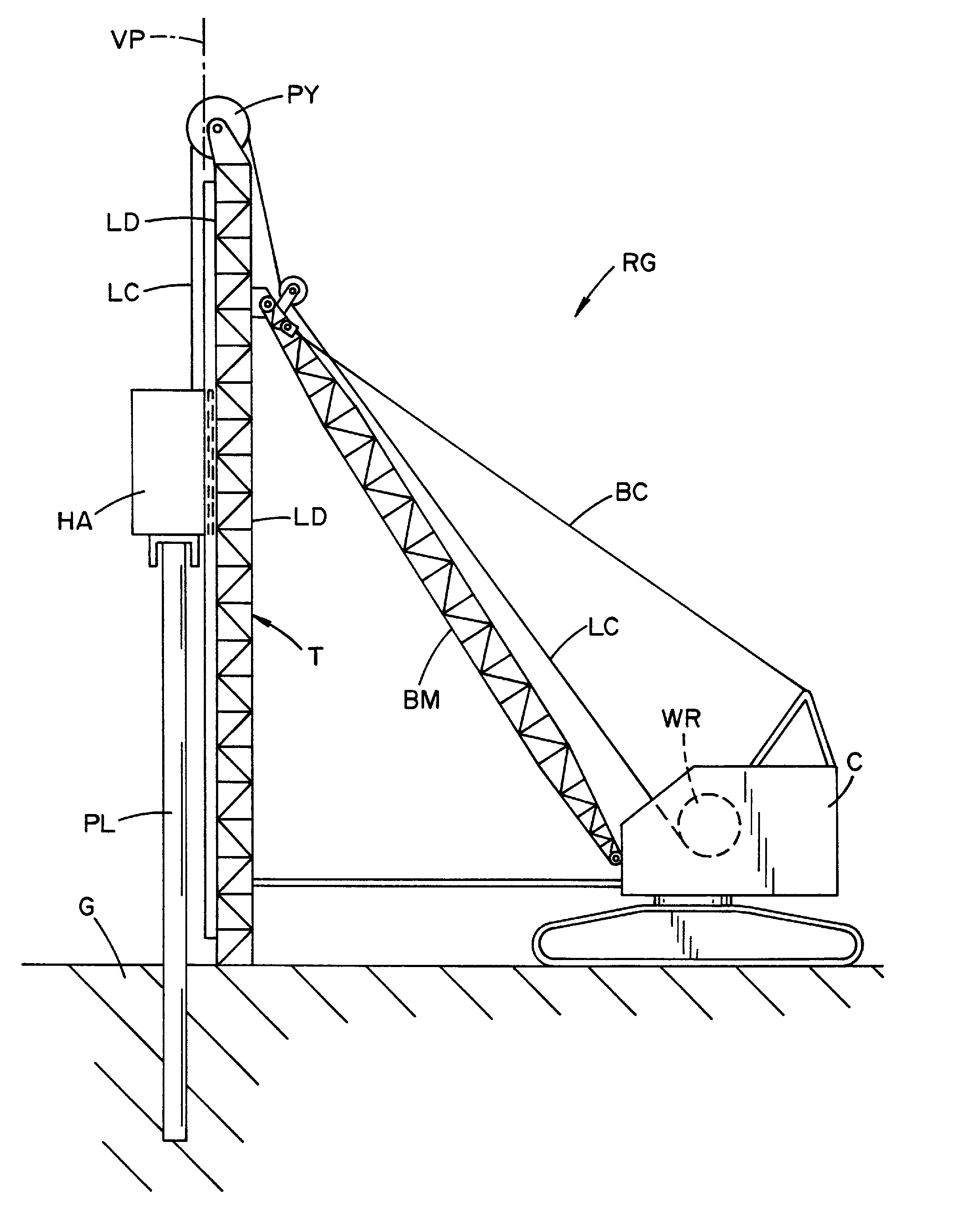
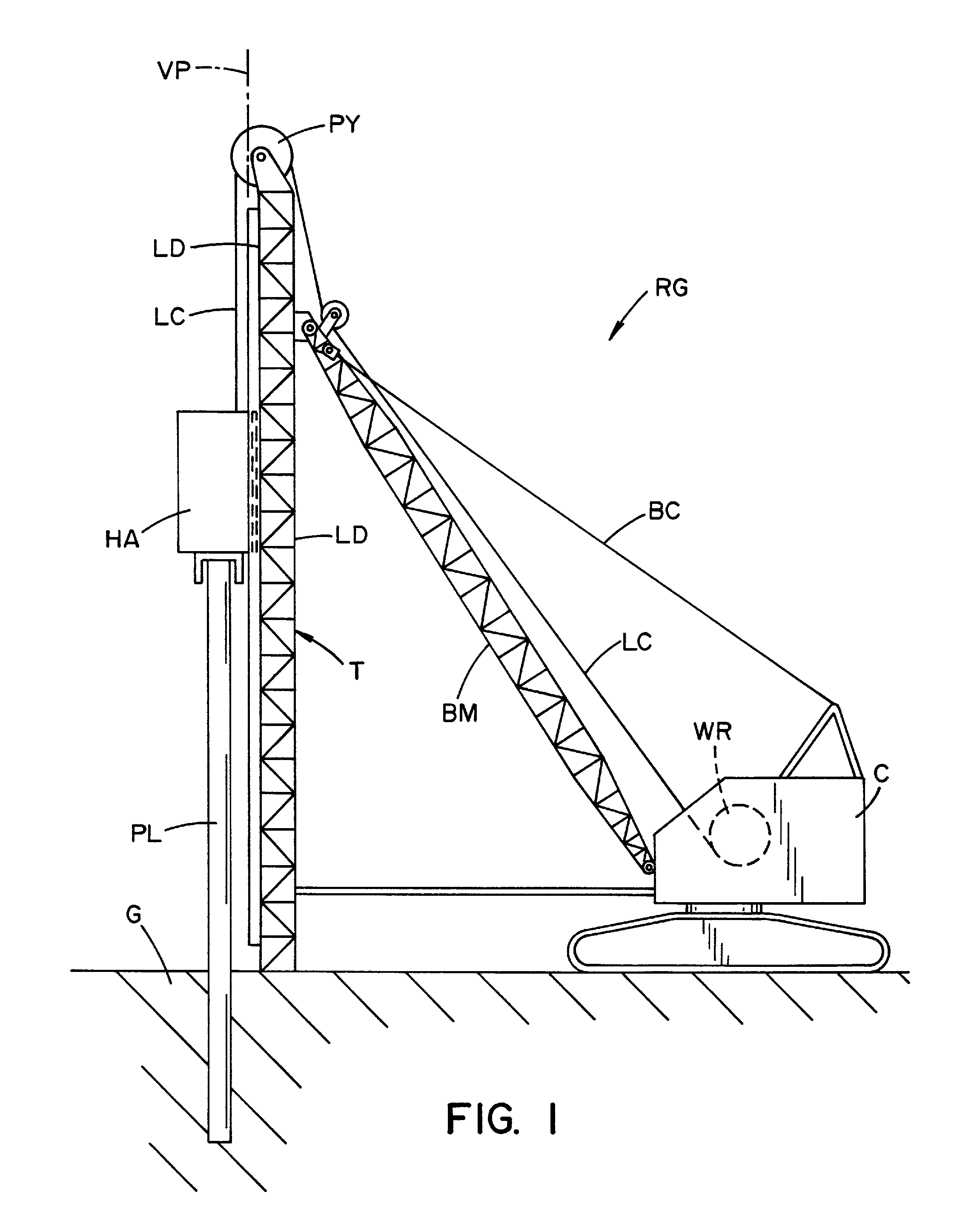
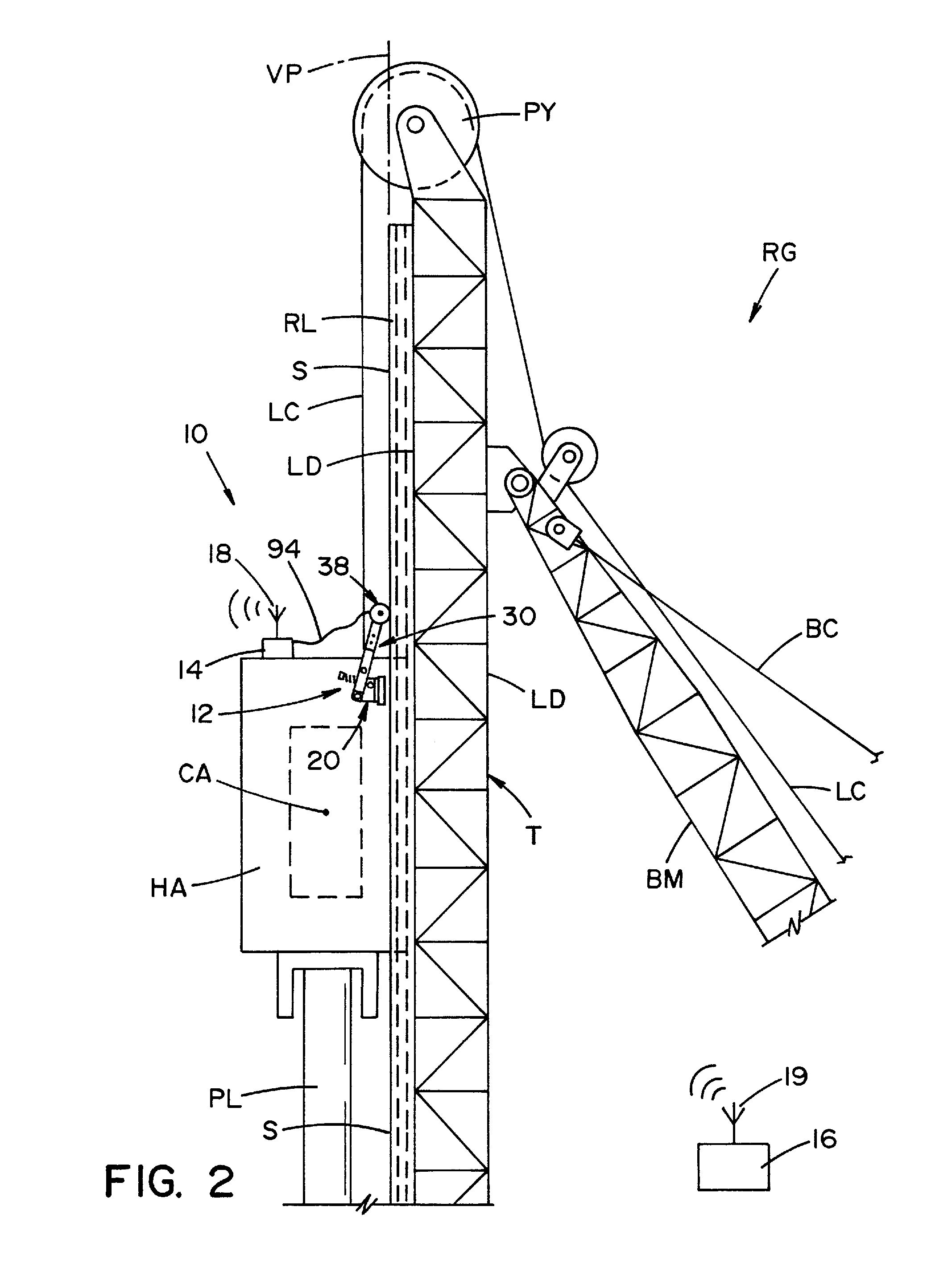
[0044]Referring now to the drawings wherein the showings are for the purpose of illustrating preferred and alternative embodiments of the invention only and not for the purpose of limiting same, FIGS. 1, 2 and 5-8 show several views of a rig or pile installation machine RG including a measuring device according to several embodiment of this applications. However, while the invention of this application is being shown in connection with a hammer rig, the invention of this application can be used in connection with other machines including an auger cast pile installation machine.

[0045]More particularly, shown is measurement device 10 at least partially mounted to rig RG and the measuring device including an encoder assembly 12, a communication system 14 and a computer system 16. In the embodiment shown in FIG. 2, communication system 14 has a wireless system 18 in communication with a computer system 16 that also has a wireless system 19. The communication system can be any communicat...


PUM


Abstract

A measurement device system and method of using the same for determining the depth of a pile being installed and / or the equipment used to install the pile. The device including an encoder assembly having a support attachable to a structural component of a rig wherein the support has a pivot joint coaxial with a load arm axis. The encoder assembly has a load arm rotatable about the arm axis and with a wheel near its distal end that is rotatable about a wheel axis with an encoder joined to the wheel that moves with the wheel. The encoder assembly further including a biasing assembly to urge the load arm and wheel into an engaged condition relative to the associated pile installation machine such that the wheel frictionally engages a surface of another structural component of the rig. Thus, the displacement of the first structural component relative to the second component rotates the wheel about the wheel axis and the encoder. This information can then be used to determine pile depth.

Description

[0001]This application claims priority to provisional patent application Ser. No. 61 / 356,396 filed on Jun. 18, 2010 which is hereby incorporated by reference.[0002]The invention of this application relates to measuring devices and, more particularly, to a measuring device configured to work in connection with a wide range of pile installation recording and installation systems.[0003]It is known in the art that the precise monitoring of the installation process of a pile or other structural member is important to both ensure that the completed pile is structurally sound and meets the specification for the particular superstructure that it is intended to support. Further, by accurately monitoring the installation process, it is not necessary to include large safety factors for the installed pile. As can be appreciated, when a pile is installed without monitoring systems or without accurate monitoring systems, a significant safety factor must be factored into the completed pile structu...

Claims


Application Information

Patent Timeline
Patent Type & Authority Patents(United States)
IPC IPC(8): G01B5/18
CPCG01B21/18
Inventor DALTON, WAYNERAINES, TIM
Owner PILE DYNAMICS
Why Eureka
Try Eureka