

Floating foundation supporting framework with buoyancy components, having an open-relief design
a technology of floating foundation and supporting framework, which is applied in the direction of floating buildings, artificial islands, vehicles, etc., can solve the problems of large weight of large plants such as medium-performance and high-performance wind power plants, and achieve the effect of reducing vibration and increasing mass inertia
- Summary
- Abstract
- Description
- Claims
- Application Information
AI Technical Summary
Benefits of technology
Problems solved by technology
Method used
Image

Examples
Embodiment Construction
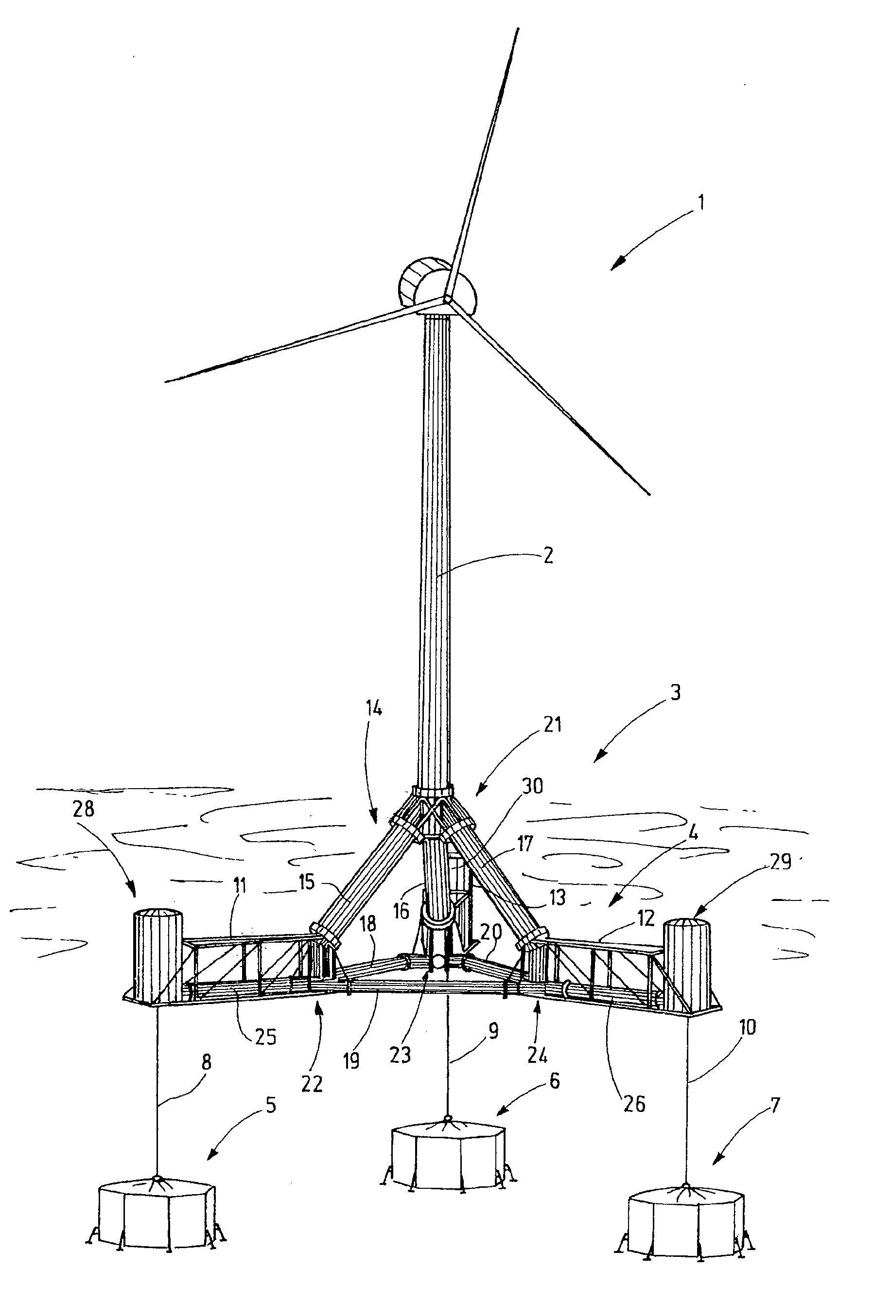
[0008]The supporting framework comprises buoyancy elements, at least one of which is at least partially made of concrete, and connecting elements, which are made of steel and which form a supporting framework. By making the buoyancy elements at least partially of concrete, it is possible to considerably lower the manufacturing costs.
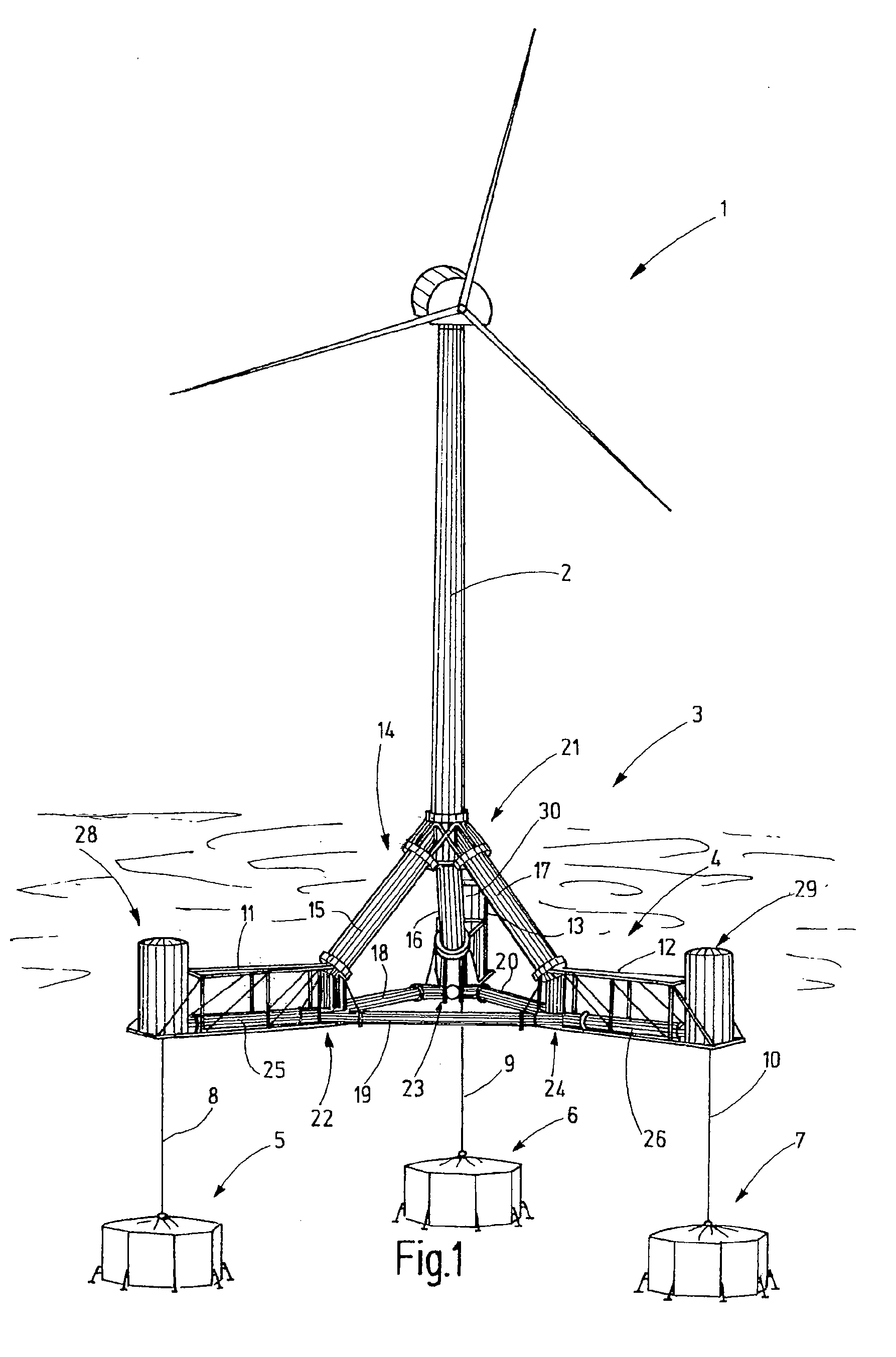
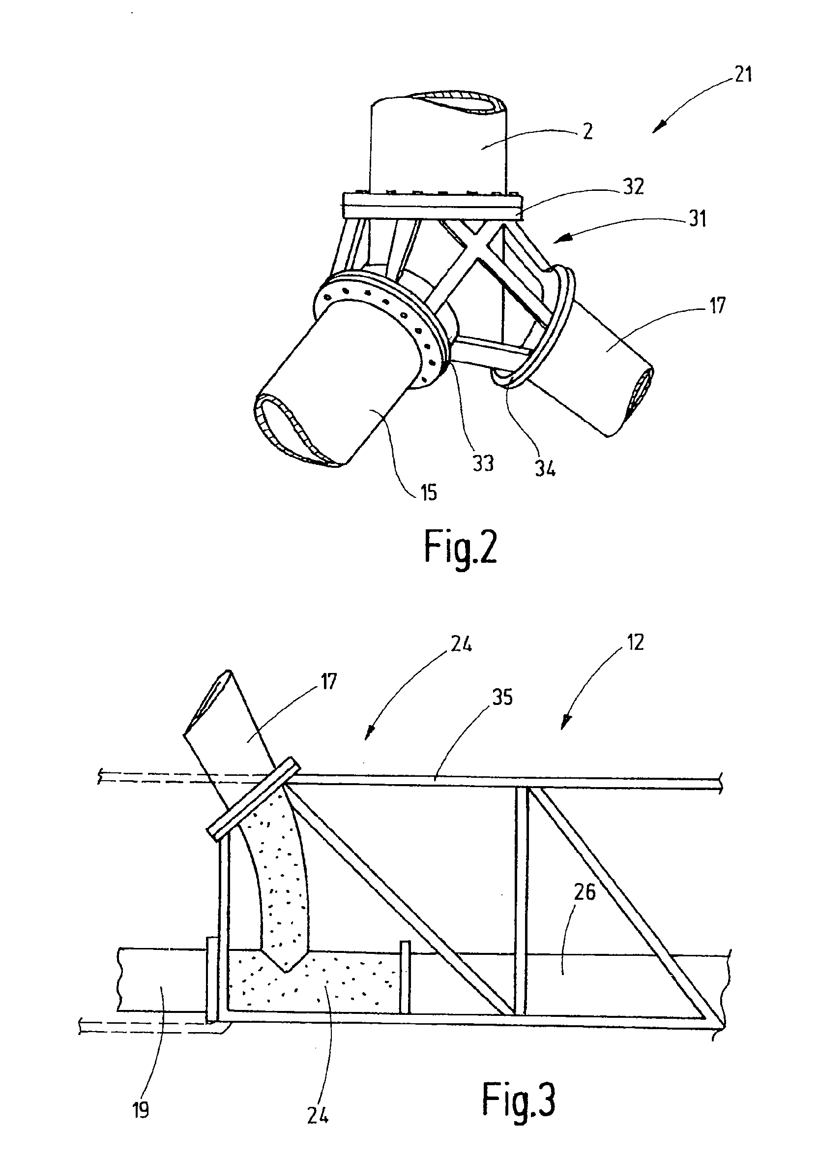
[0009]This applies, in particular, to geometrically complex shapes such as, for example, the junction regions that must be designed to be hollow in order to make walking on the structure possible. This also applies to buoyancy elements that are located at the outer ends of a supporting framework that is star-shaped, for example, in order to introduce buoyancy forces into the supporting framework at that location. In particular, the lower parts or bottoms of buoyancy elements may be made of concrete. Due to the rigidity of reinforced concrete elements, such elements may have a flat bottom or a bottom that is only slightly arched, for example.
[0010]The use...
PUM
| Property | Measurement | Unit |
|---|---|---|
| depth | aaaaa | aaaaa |
| diameter | aaaaa | aaaaa |
| reciprocal opening angle | aaaaa | aaaaa |
Abstract
Description
Claims
Application Information