NF3 chamber clean additive

a technology of additives and chambers, applied in the field of nf3 chamber clean additives, can solve the problems of reducing the ability of nf/sub>3/sub>to reform, reducing the quantity of discarded nf/sub>3/sub>, etc., and achieve the effect of reducing the ability of nf3 to reform and enhancing the chamber-cleaning effect of nf3

Inactive Publication Date: 2014-01-07
MATHESON TRI GAS INC
View PDF34 Cites 66 Cited by
  • Summary
  • Abstract
  • Description
  • Claims
  • Application Information

AI Technical Summary

Benefits of technology

[0005]Methods of cleaning a chemical vapor deposition (CVD) chamber with nitrogen trifluoride (NF3) are described. The methods involve a concurrent introduction of nitrogen trifluoride and a reactive diluent into a CVD chamber. The NF3 may be excited in a plasma inside the CVD chamber or in a remote plasma region upstream from the CVD chamber. The reactive diluent may be introduced upstream or downstream of the remote plasma such that both NF3 and the reactive diluent (and any plasma-generated effluents) are present in the CVD chamber during cleaning. The presence of the reactive diluent enhances the chamber-cleaning effectiveness of the NF3 which allows less NF3 to be used and discarded. The reactive diluent may also reduce the ability of the NF3 to reform and therefore, further reduce the quantity of discarded NF3.
[0007]Embodiments may also include methods of cleaning a CVD chamber with NF3. The method may include introducing a cleaning mixture to the CVD chamber, wherein the cleaning mixture comprises the NF3 or reactive species generated from the NF3 and a replacement compound selected from the group consisting of COF2, IF5, F2, NCl2F, NI2F, (CH3)2NF, (CF3)2NF, NOF2, BrF3, IF, and ClF to the CVD chamber. The methods may further include reacting the cleaning mixture and the replacement compound with a contaminant in the CVD chamber to form a reacted contaminant which is removed from the CVD chamber. A presence of the replacement compound results in less NF3 exhausted from the CVD chamber following reaction with the contaminant.

Problems solved by technology

The reactive diluent may also reduce the ability of the NF3 to reform and therefore, further reduce the quantity of discarded NF3.

Method used


Image

  • NF3 chamber clean additive
  • NF3 chamber clean additive
  • NF3 chamber clean additive

Examples


Embodiment Construction

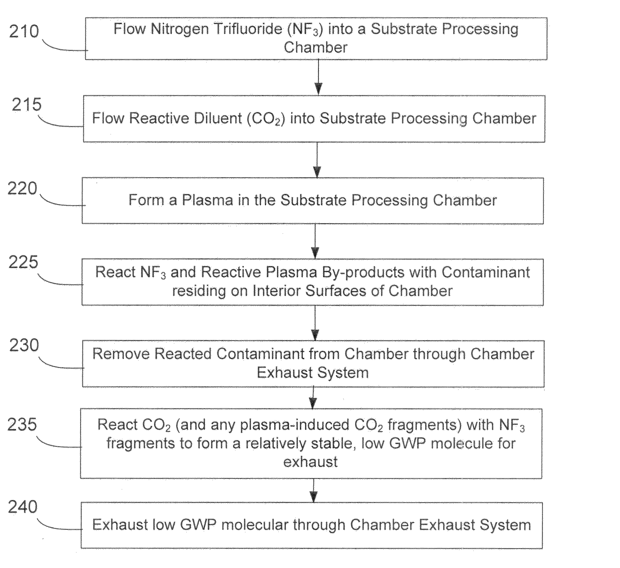
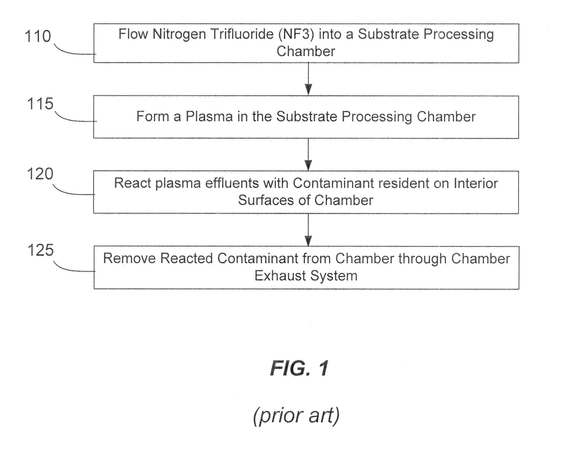
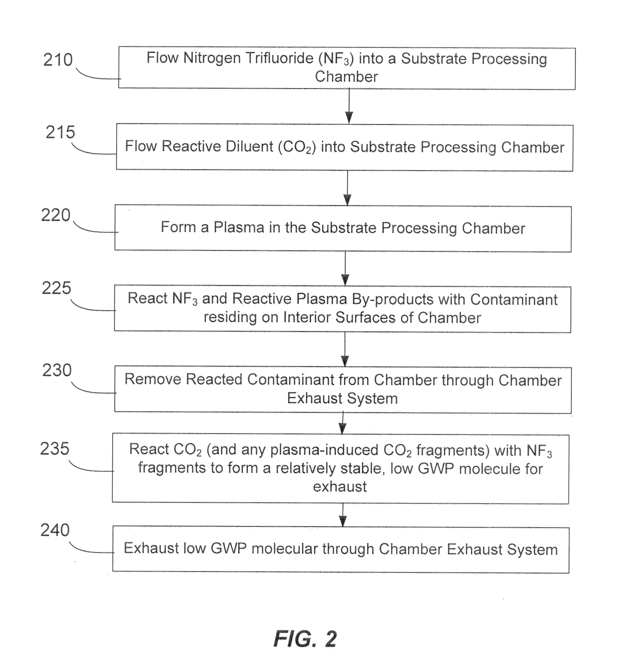
[0016]Methods of cleaning a process chamber with nitrogen trifluoride (NF3) are described. The methods involve a concurrent introduction of nitrogen trifluoride and a reactive diluent into a process chamber. The NF3 may be excited in a plasma inside the chamber or in a remote plasma region upstream from the chamber. The reactive diluent may be introduced upstream or downstream of the remote plasma such that both NF3 and the reactive diluent (and any plasma-generated effluents) are present in the chamber during cleaning. The presence of the reactive diluent enhances the chamber-cleaning effectiveness of the NF3 which allows less NF3 to be used and discarded. The reactive diluent may also reduce the ability of the NF3 to reform and therefore, further reduce the quantity of discarded NF3. Exemplary chambers may include chemical vapor deposition (CVD) chambers, physical vapor deposition (PVD) chambers, and atomic-layer deposition (ALD) chambers, among other kinds of process chambers.

[00...


PUM

PropertyMeasurementUnit
GWPaaaaaaaaaa
etch rateaaaaaaaaaa
electro-mechanical propertiesaaaaaaaaaa

Abstract

Methods of cleaning a processing chamber with nitrogen trifluoride (NF3) are described. The methods involve a concurrent introduction of nitrogen trifluoride and a reactive diluent into the chamber. The NF3 may be excited in a plasma inside the chamber or in a remote plasma region upstream from the chamber. The reactive diluent may be introduced upstream or downstream of the remote plasma such that both NF3 and the reactive diluent (and any plasma-generated effluents) are present in the chamber during cleaning. The presence of the reactive diluent enhances the chamber-cleaning effectiveness of the NF3.

Description

CROSS-REFERENCES TO RELATED APPLICATIONS[0001]This application claims the benefit of U.S. Prov. Pat. App. No. 61 / 241,287 filed Sep. 10, 2009, and titled “ETCH AND CLEAN PROCESSES,” which is incorporated herein by reference for all purposes.BACKGROUND OF THE INVENTION[0002]The semiconductor industry has benefited from in-situ dry cleaning procedures made possible by exciting nitrogen trifluoride in a plasma and flowing the plasma effluents to clean interior surfaces of a substrate processing chamber. In-situ cleaning procedures avoid requiring chamber disassembly while still removing undesired substances such as silicon nitride, polycrystalline silicon, silicides and silicon dioxide. Removing these undesired substances before additional substrate processing may reduce defects and control electro-mechanical properties of processed layers.[0003]A prior art chamber cleaning procedure is shown in FIG. 1 and begins when nitrogen trifluoride is flowed into a substrate processing chamber (o...

Claims


Application Information

Patent Timeline
Patent Type & Authority Patents(United States)
IPC IPC(8): B08B9/00
CPCH01J37/32862C23C16/4405H01J37/32357
Inventor MITCHELL, GLENNTORRES, JR., ROBERTSEYMOUR, ADAM
Owner MATHESON TRI GAS INC
Why Eureka
Try Eureka