Atmospheric water harvesters
a water harvester and atmosphere technology, applied in the field of atmospheric water harvesters, can solve the problems of low efficiency, low efficiency, and low efficiency of water harvesting, and achieve the effect of robust design and construction, and good air quality
- Summary
- Abstract
- Description
- Claims
- Application Information
AI Technical Summary
Benefits of technology
Problems solved by technology
Method used
Image

Examples
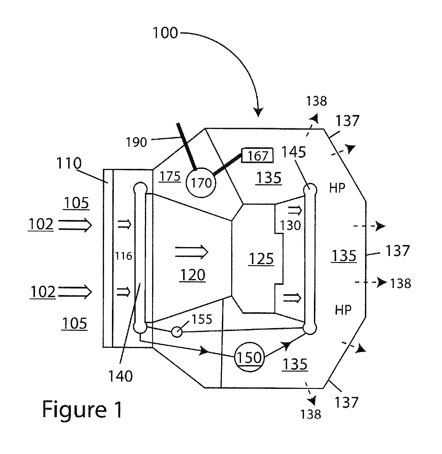
embodiment 100
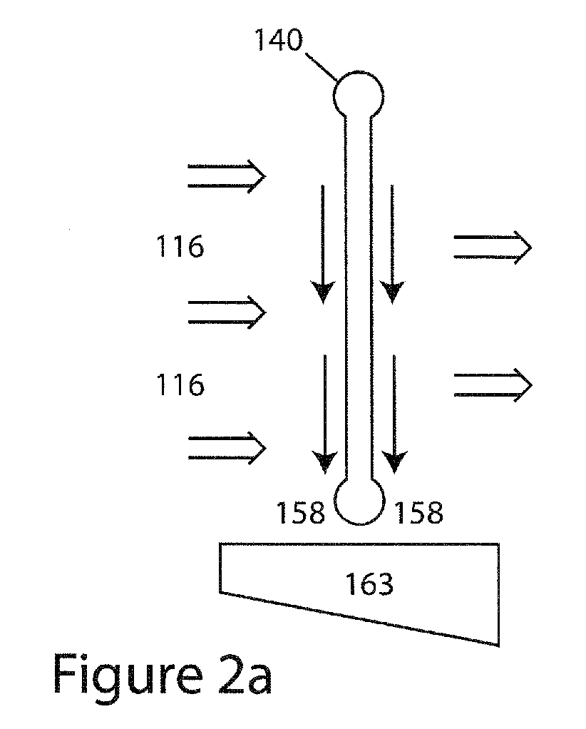
[0019]In the AWH embodiment 100 shown in FIG. 1, the evaporator 140 is in a vertical orientation, as shown in FIG. 2a. Water (black, single stem arrows) 158 formed on the upper evaporator surfaces flows down over the subjacent evaporator surfaces, which has the effect of amalgamating the water into rivulets as well as droplets as it flows from the evaporator 140 to the subjacent water collector 163. Because rivulets are more coherent water masses with higher mass to surface area ratios, they are less liable to lose water to the airstream moving at about a 90 degree angle across the flowing condensed water. Additionally, the water passing from the evaporator 140 to the water collection tank 163 may be only very slightly affected by air flow, which does not impinge toward the water collection tank 163.
[0020]With an alternate orientation of the evaporator as shown in FIG. 2b, water is removed from a horizontally oriented evaporator (also labeled 140) by forced air moving in the same di...
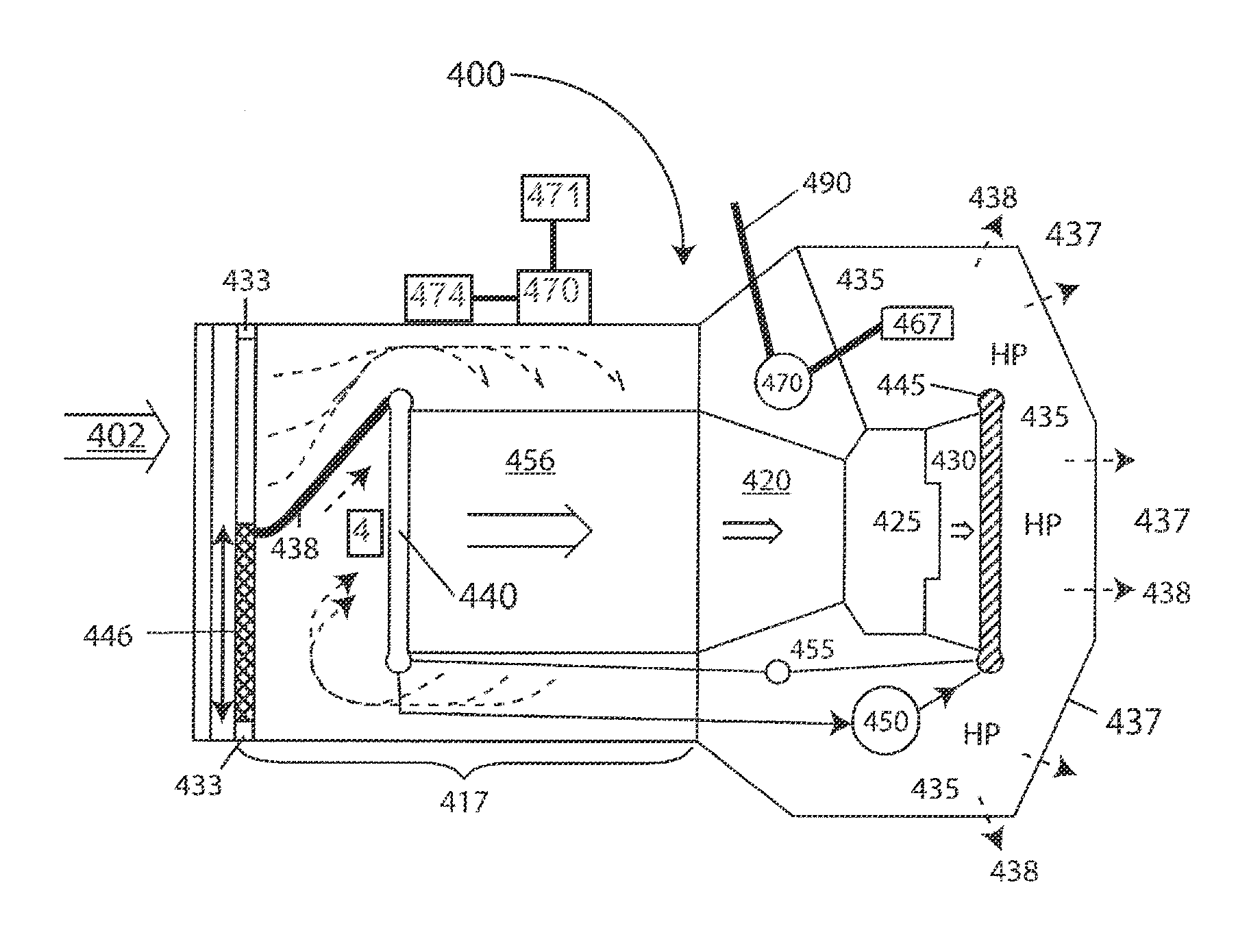
embodiment 400
[0026]Two further embodiments 200, 300 will be described with reference to FIGS. 3 and 4, respectively, in which there are slight variations in the handling of air within the AWH following extraction of water from it. In these embodiments 200, 300 (as well as in another embodiment 400, as described below), similar system components are similarly numbered, but increased to the corresponding hundreds series to “match” the embodiment number 200, 300, 400. Unless otherwise described, the similarly numbered components are the same as or generally similar to those described above and may have similar attributes.
[0027]Where an AWH must be operated in very hot ambient temperatures, or where a compressor that requires external cooling is used, forced-air cooling may be provided by controlling airflow in two general manners. These are shown in FIG. 3, in which an embodiment 200 uses existing exhaust for cooling of the compressor 250, and in FIG. 4, in which an embodiment 300 uses a supplement...
PUM
 Abstract
Description
Claims
Application Information