
High frequency triode-type field emission device and process for manufacturing the same

a triode-type, high-frequency technology, applied in the direction of control electrodes, discharge tubes luminescnet screens, electric discharge lamps, etc., can solve the problems of limiting the operating frequency that this type of device can reach, and making thz applications, even for micron scaled structures, substantially unfeasible, etc., to achieve the effect of reducing the cut-off frequency and limiting the operating frequency

Inactive Publication Date: 2014-01-14
SELEX SISTEMI INTEGRATI
View PDF5 Cites 3 Cited by
  • Summary
  • Abstract
  • Description
  • Claims
  • Application Information

AI Technical Summary

Benefits of technology

The patent text discusses the issue that limitations exist in the structure of Spindt-type vacuum tube triodes due to the presence of large parasitic capacitances. The objective of the patent is to provide an innovative topographical configuration and manufacturing process to overcome these limitations. The invention achieves this by reducing the area of overlap between the cathode and anode electrodes, and the control gate, which results in a reduction of overall parasitic capacitance. This allows for higher operating frequencies, making THz applications, even for micron scaled structures, feasible.

Problems solved by technology

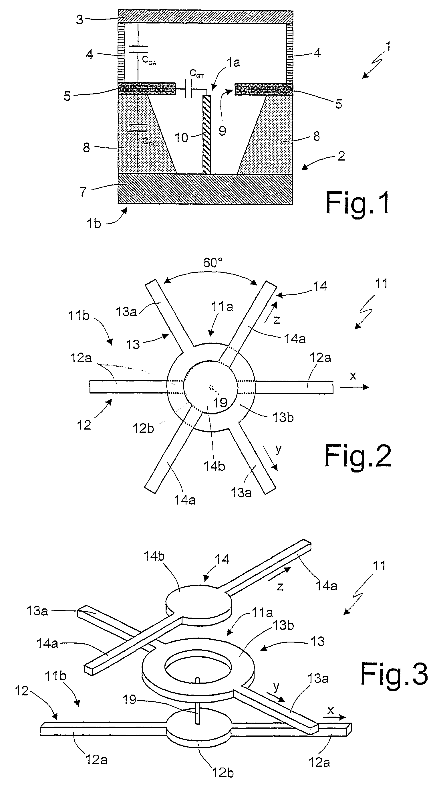
The Applicant has noticed that the topographic configuration of known Spindt-type vacuum tube triode devices suffers from an important limitation, due to the large value of parasitic capacitances existing between the control gate and the cathode and anode electrodes.
This parasitic capacitance heavily limits the operating frequency that this type of device can reach, reducing the cut-off frequency, and making THz applications, even for micron scaled structures, substantially unfeasible.
From the foregoing, it is evident that the operating frequency of this type of device is heavily dependent on, and strongly limited by, its topographic characteristics.

Method used


Image

  • High frequency triode-type field emission device and process for manufacturing the same
  • High frequency triode-type field emission device and process for manufacturing the same
  • High frequency triode-type field emission device and process for manufacturing the same

Examples


first embodiment

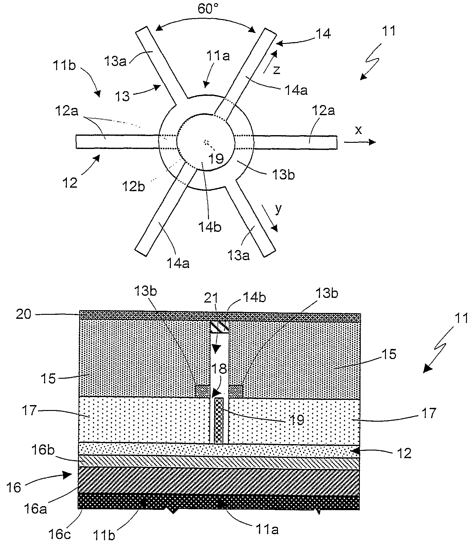
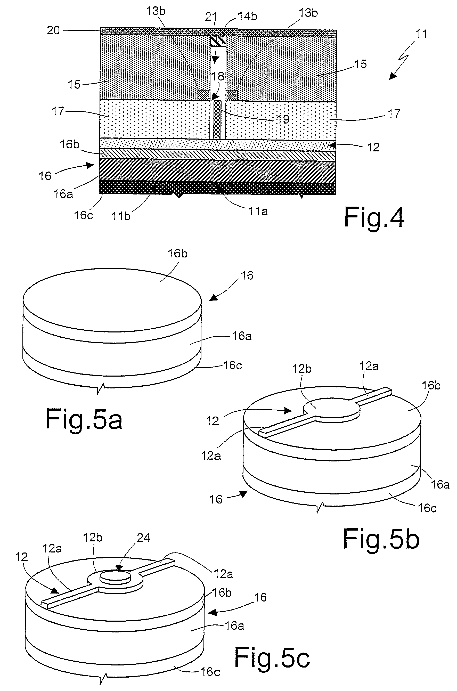
[0030]The following discussion is presented to enable a person skilled in the art to make and use the invention. Various modifications to the embodiments described will be readily apparent to those skilled in the art, and the generic principles herein may be applied to other embodiments and applications without departing from the spirit and scope of the present invention. Thus, the present invention is not intended to be limited to the embodiments shown, but is to be accorded the widest scope consistent with the principles and features disclosed herein and defined in the attached claims. FIGS. 2 and 3 show respectively a schematic top view and a perspective exploded view of a high-frequency triode-type field emission device 11 according to the present invention and defined as having a “crossbar structure”, while FIG. 4 shows a cross sectional view of the high frequency triode-type field emission device 11, in accordance with the present invention.

[0031]In detail, according to the fi...

second embodiment

[0050]A possible variant of this second embodiment, FIG. 7, may provide for the ground plane (conducting layer 16a) to be coupled to the insulating substrate 20; the cathode electrode 12 is in this case patterned on the multilayer structure made by the insulating substrate 20 formed on the conducting layer 16a. The anode electrode 14, which is integrated with the control gate electrode 13, is instead formed on the insulating layer 16b.

[0051]FIG. 8 shows a further embodiment of the present invention, envisaging the formation of an array 25 of a large number of high-frequency triode-type field emission devices 11, having the previously described “cross-bar structure”.

[0052]In detail, the high-frequency triode-type field emission devices 11 of the array 25 are aligned along the first, second and third direction x, y, z. Each of the high-frequency triode-type field emission devices 11 in the array 25 shares its cathode, gate and anode conduction lines 12a, 13a, 14a, with other devices,...


PUM


Abstract

Disclosed herein is a triode-type field emission device, in particular for high frequency applications, having a cathode electrode, an anode electrode spaced from the cathode electrode, a control gate electrode arranged between the anode electrode and the cathode electrode, and at least a field-emitting tip; the cathode, control gate and anode electrodes overlapping in a triode area at the field-emitting tip and being operable to cooperate with the field-emitting tip for generation of an electron beam in the triode area. The cathode, control gate and anode electrodes do not overlap outside the triode area, and have a main direction of extension along a respective line; each of these respective lines being inclined at a non-zero angle with respect to each one of the others.

Description

TECHNICAL FIELD OF THE INVENTION[0001]The present invention relates in general to a micro / nanometrical device belonging to the family of semiconductor vacuum tubes for high frequency applications, and more particularly to an innovative high frequency triode-type field emission device, and to a process for manufacturing the same.BACKGROUND ART[0002]As is known, technology and applications in the THz frequency range have traditionally been restricted to the field of molecular astronomy and chemical spectroscopy. However, recent advances in THz detectors and sources have opened the field to new applications, including homeland security, measurement systems (network analysis, imaging), biological and medical applications (cell characterization, thermal and spectral mapping), material characterization (near-field probing, food industry quality control, pharmaceutical quality control).[0003]Although commercial uses for THz sensors and sources are growing, this growth is somehow limited by...

Claims


Application Information

Patent Timeline
Patent Type & Authority Patents(United States)
IPC IPC(8): H01J27/00H01J1/62
CPCH01J21/105H01J21/20
Inventor DI CARLO, ALDOPAOLINI, CLAUDIOPETROLATI, ELEONORABRUNETTI, FRANCESCARICCITELLI, RICCARDO
Owner SELEX SISTEMI INTEGRATI
Learn More