

Resonator element, resonator, physical quantity sensor, and electronic equipment that have steps on a side surface of a vibrating arm
a technology of resonator and side surface, which is applied in the direction of turn-sensitive devices, instruments, and device material selection, etc., can solve the problems of deteriorating electric field efficiency, difficult to form electrodes in the side surface direction, and increasing vibration loss
- Summary
- Abstract
- Description
- Claims
- Application Information
AI Technical Summary
Benefits of technology
Problems solved by technology
Method used
Image

Examples
embodiment 1
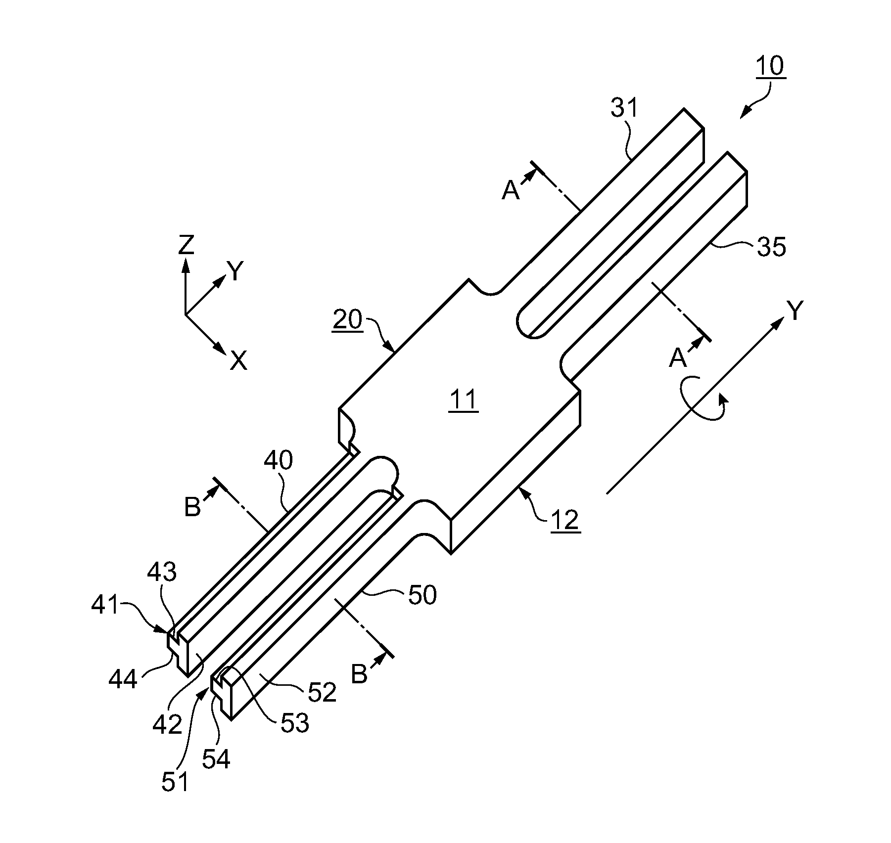
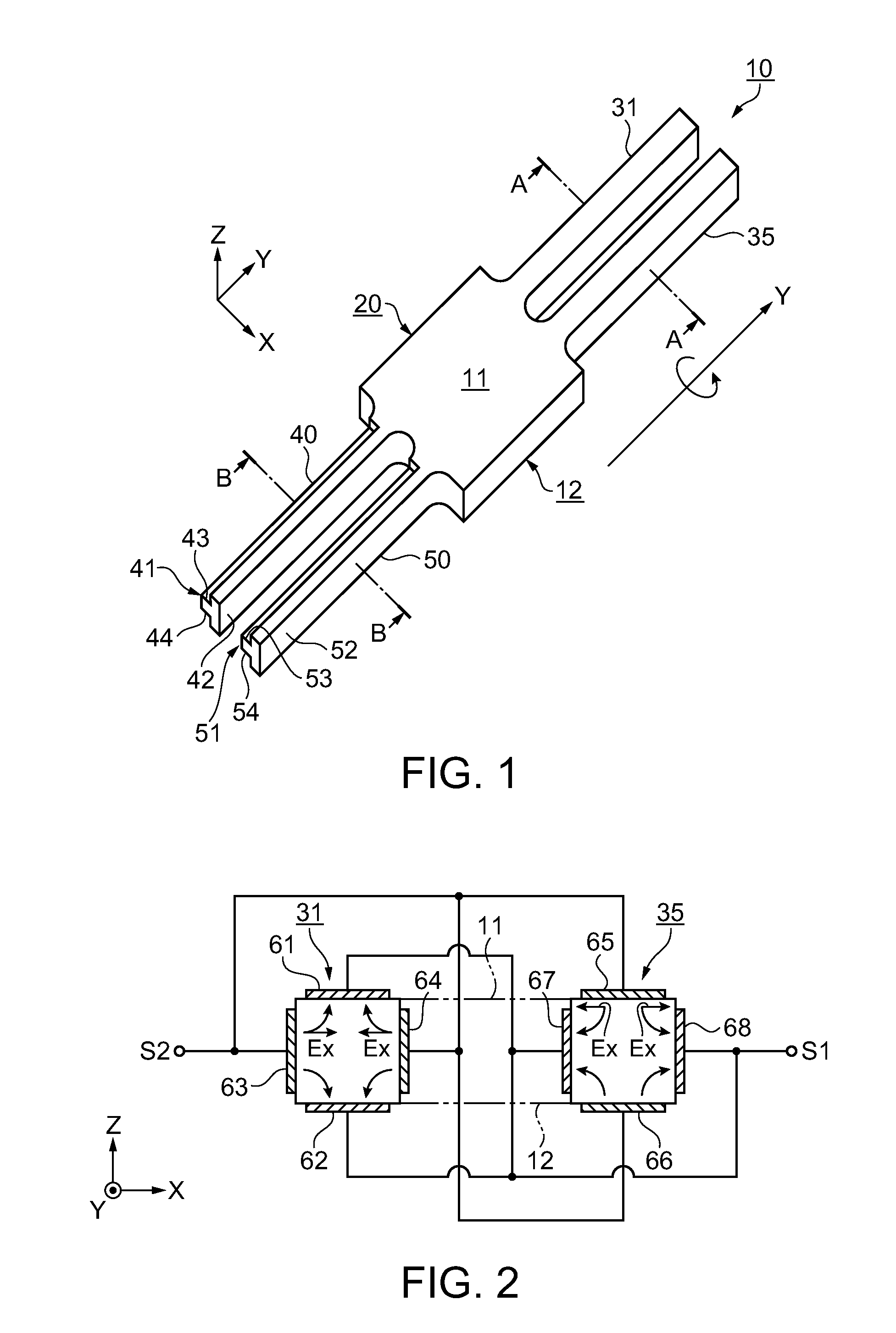
[0058]FIG. 1 is a perspective view showing a resonator element according to embodiment 1, FIG. 2 is a sectional view showing A-A section of FIG. 1, and FIG. 3 is a sectional view showing B-B section of FIG. 1. First, an overall configuration of the resonator element will be explained with reference to FIG. 1.
[0059]A resonator element 10 of the embodiment is extended on a plane formed by the X-axis (the second axis) and the Y-axis (the first axis) orthogonal to the X-axis on the plane, and has a first principal surface 11 and a second principal surface 12 opposed to each other. The axis perpendicular to the first principal surface 11 and the second principal surface 12 is the Z-axis. In the case where the resonator element 10 is made of quartz, the X-axis is the electric axis, the Y-axis is the machine axis, and the Z-axis is the optical axis. The resonator element 10 includes a first vibrating arm 31 and a second vibrating arm 35 extended in +Y direction and a third vibrating arm 40...
modified example of embodiment 1
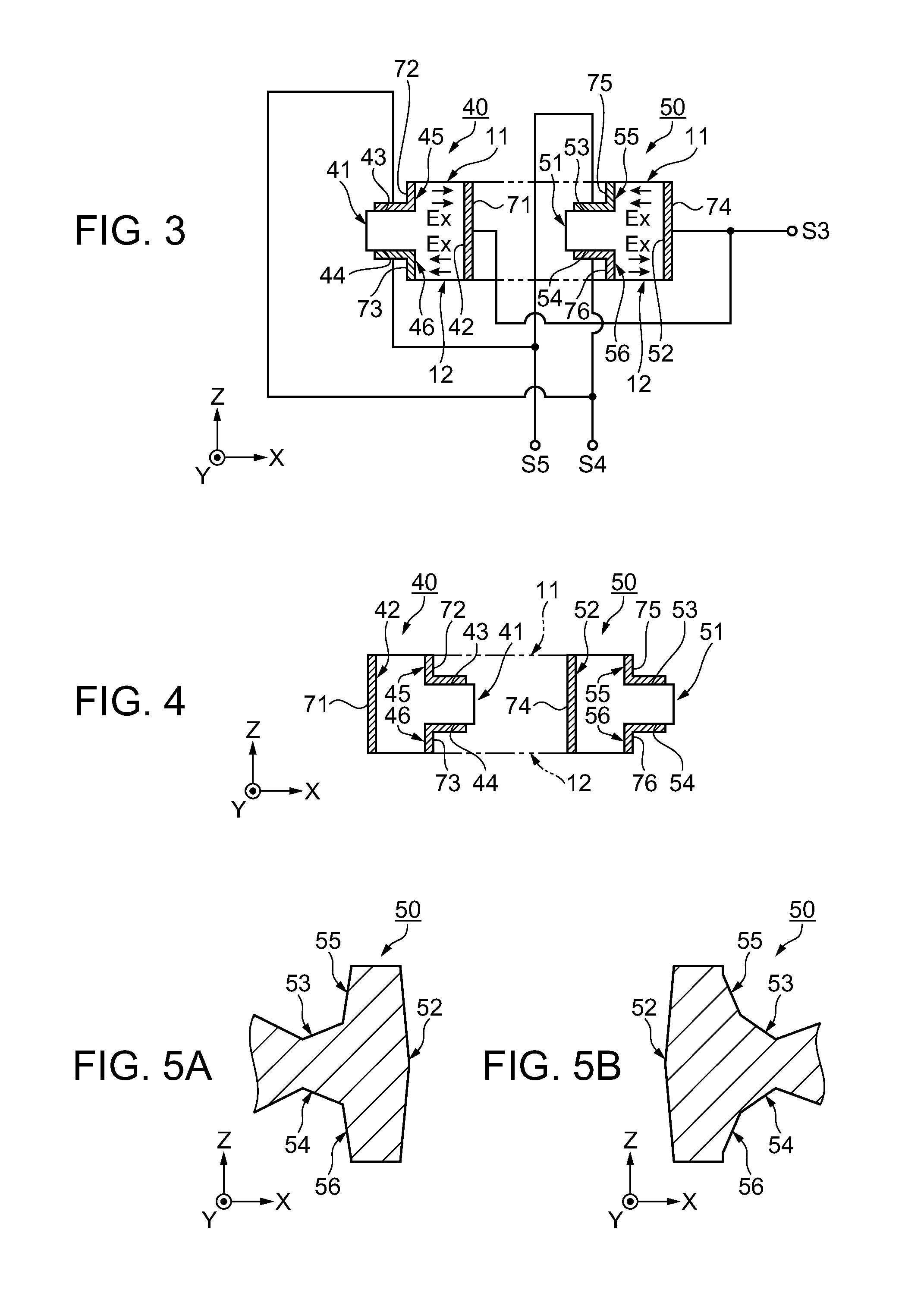
[0082]Subsequently, a modified example of embodiment 1 will be explained. In the modified example, the first and second step parts 43 and 44 and the third and fourth step parts 53 and 54 are provided in the +X direction of the first detection arm 40 and the second detection arm 50. Accordingly, the differences from embodiment 1 will be centered in the explanation. Further, the same signs are assigned to the parts having the same functions.
[0083]FIG. 4 is a sectional view showing the first detection arm and the second detection arm according to the modified example. Note that FIG. 4 is the sectional view corresponding to the B-B section position of FIG. 1. On the first detection arm 40, the first step part 43 drilled from the first principal surface 11 to the side surface 41 in the +X direction and the second step part 44 drilled from the second principal surface 12 to the side surface 41 in the +X direction are formed. The first step part 43 and the second step part 44 are formed ov...
embodiment 2
[0091]Subsequently, a resonator element according to embodiment 2 will be explained with reference to the drawings. While the above described embodiment 1 has the H-shaped tuning fork configuration, embodiment 2 has a double-turning fork configuration.
[0092]FIG. 6 is a plan view showing the resonator element according to embodiment 2, and FIG. 7 is a sectional view showing A-A section of FIG. 6. The resonator element 110 includes two vibrating arms 131, 140 extended from a base part 120 in parallel in the +Y direction. Here, the vibrating arm 131 has a rectangular sectional shape and excitation electrodes, and corresponds to the first vibrating arm 31 of the above described embodiment 1 (see FIGS. 1 and 2). The vibrating arm 140 has a configuration having step parts and detection electrodes as a detection arm, and corresponds to the second detection arm 50 of embodiment 1 (see FIGS. 1 and 3). Accordingly, the vibrating arm 140 will be referred to as “detection arm 140” for explanati...
PUM
 Abstract
Description
Claims
Application Information