Component having a micromechanical microphone structure, and method for its production

a micromechanical and microphone technology, applied in the direction of generator/motor, semiconductor electrostatic transducer, semiconductor/solid-state device details, etc., can solve the problems of high fragility of the conventional microphone component, inability to use these components without additional protective measures, and cost-efficient circular sawing with the aid of water-cooled circular saw, which is very common, and achieves high selectivity of the etching process. , the effect of high etching speed and large under-etching width

Inactive Publication Date: 2014-01-28
ROBERT BOSCH GMBH
View PDF22 Cites 9 Cited by
  • Summary
  • Abstract
  • Description
  • Claims
  • Application Information

AI Technical Summary

Benefits of technology

[0006]In accordance with the present invention, a component having a robust but acoustically sensitive microphone structure is provided and a simple and cost-effective method for its production.
[0008]According to an example embodiment of the present invention, an advantageous effect on the rigidity of the counter element of the microphone structure comes about if the counter element is developed in a relatively thick layer, which extends across the entire component surface and compensates for differences in level. In this case, the counter element is integrated on all sides at the same rigidity, the rigidity essentially depending solely on the layer thickness. The thicker the layer, the stiffer the counter element, the more firmly the counter element is integrated in the layer configuration of the component and the better the leveling effect, especially in the edge region of the counter element.
[0009]According to an example embodiment of the present invention, the production of the microphone structure of the conventional component modified in this manner is easily implemented in a sequence of processes of bulk and surface micromechanics, as already used in the production of inertial sensors. The largely level component surface, in particular, simplifies the dice-up operation of the example microphone components according to the present invention, which will be explained in greater detail in connection with the production method according to the present invention.
[0019]The use of a SiGe sacrificial layer using ClF3 as etching gas is especially advantageous due to the high selectivity of the etching process with regard to numerous materials used in micro-system technology, and with regard to silicon, in particular. This etching process is characterized by its high etching speed and the large under-etching widths obtainable in this manner. In addition, SiGe sacrificial layers are especially low in stresses, so that the use of this material also allows relatively thick sacrificial layers and thus large electrode clearances to be realized, without introducing additional stresses in the component configuration. This increases the design freedom in the configuration of the microphone component.
[0020]As mentioned already, the microphone structures according to the present invention are exposed in the wafer composite and separated only thereafter. One especially advantageous variant of the method according to the present invention utilizes the configuration of the microphone component according to the present invention, i.e., the fact that the layer in which the counter elements are realized is situated on the top surface of the layer configuration and that this layer is relatively thick as well as stable, and mostly planar according to the present invention. These layer properties allow a protective foil to be applied, which reliably prevents particles and fluid from entering the microphone structures. As a result, the microphone components are able to be diced up in a sawing process standardized in micromechanics, which yields enormous cost advantages in comparison with the methods currently used for dicing up microphone components. Following the dice-up procedure, the protective foil is removed, leaving as little residue as possible.
[0021]In this context, it is advantageous to use a protective foil which loses its adhesive strength through UV radiation or a thermal treatment or through UV radiation in combination with a thermal treatment. Such a protective foil is easily able to be laminated to the largely planar surface of the layer configuration, using a vacuum, and to be detached again from the surfaces of the components following the dice-up process with the aid of UV radiation in combination with a thermal treatment, leaving no residue and causing no damage to the microphone structures.

Problems solved by technology

The highly fragile structure of the conventional microphone component, which is sensitive to water, poses a problem in this context.
The cost-efficient sawing with the aid of a water-cooled circular saw, which is very common in micro technology, cannot be used for these components without additional protective measures.
It must be assumed that the sensitive microphone structures are unable to withstand the impinging water jet.
In addition, water that penetrates the space between the two electrodes of the microphone capacitor leads to irreversible adhesion of the diaphragm to the counter element, which also destroys the microphone function.
This requires special machinery and thus additional investment expense.
Uncontrolled stresses within the diaphragm can lead to an undesired predeflection of the diaphragm and thereby change the sensitivity-defining characteristics of the microphone capacitor.

Method used


Image

  • Component having a micromechanical microphone structure, and method for its production
  • Component having a micromechanical microphone structure, and method for its production
  • Component having a micromechanical microphone structure, and method for its production

Examples


Embodiment Construction

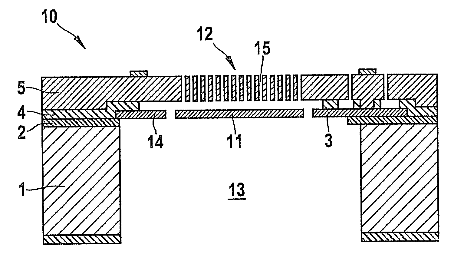
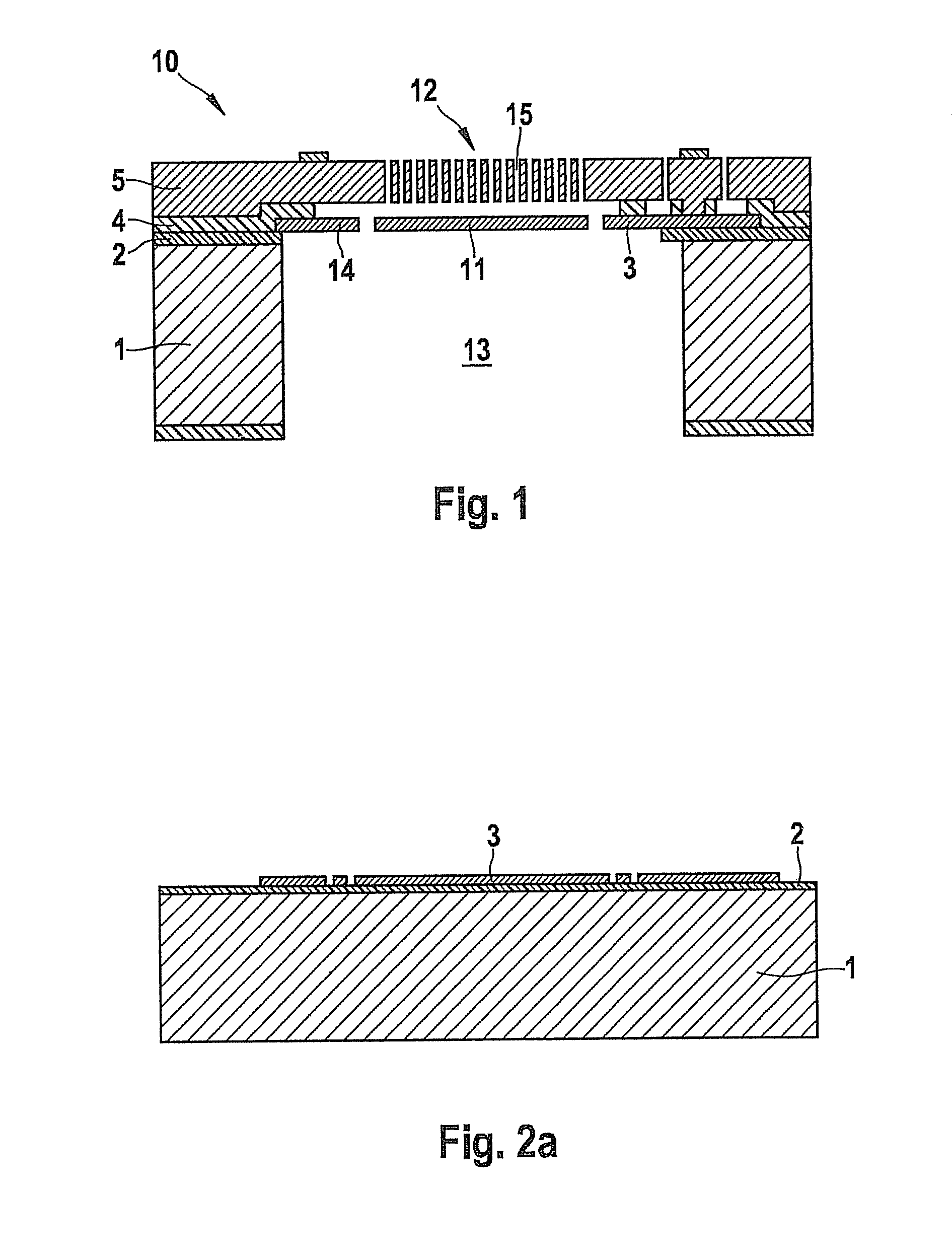
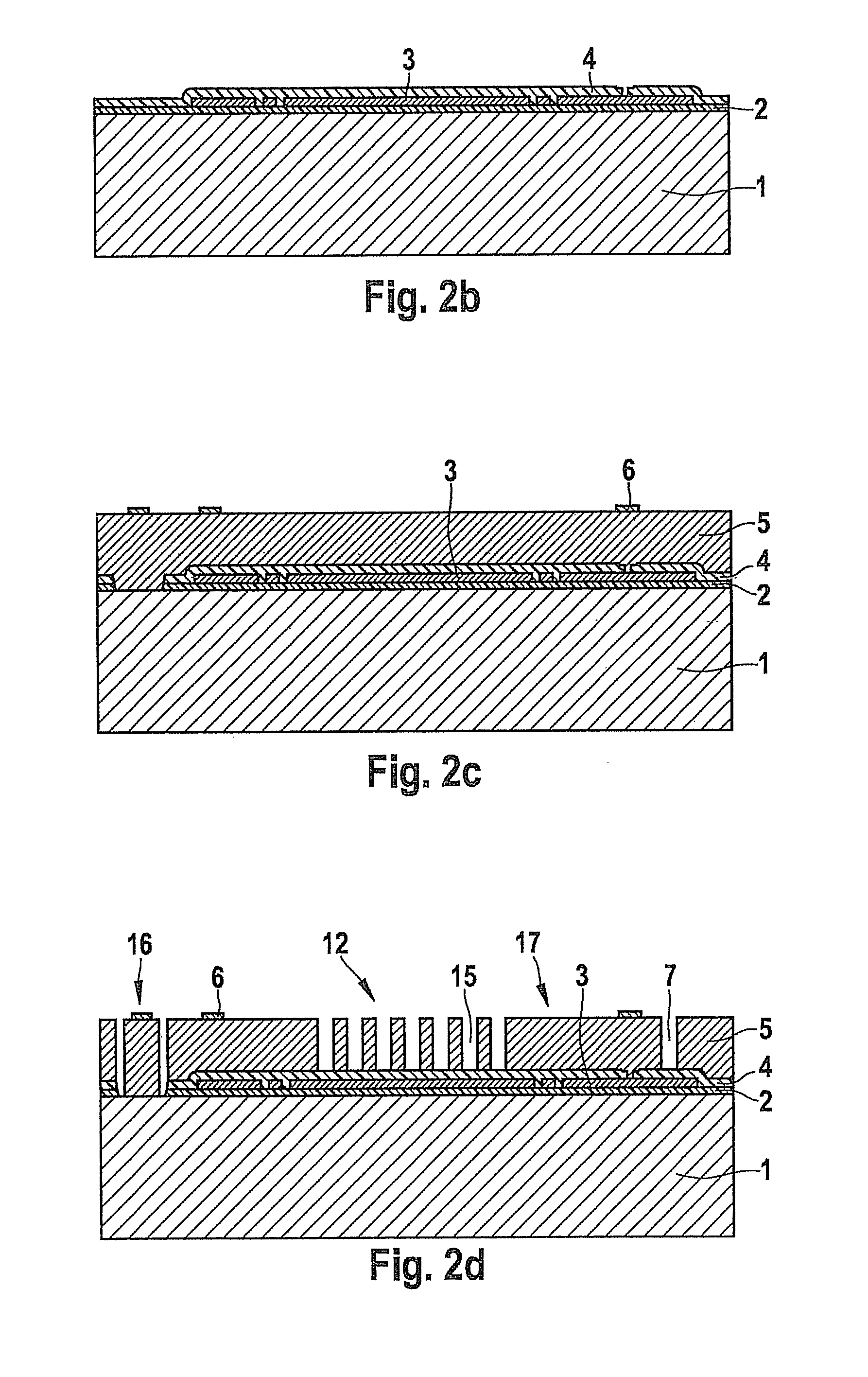
[0027]Component 10 shown in FIG. 1 includes a micromechanical microphone structure having a deflectable, acoustically active diaphragm 11, and a stationary, acoustically permeable counter element 12, which is also referred to as back plate. Here, diaphragm 11 and counter element 12 are realized in a layer configuration on a semiconductor substrate 1. A sound opening 13, which extends across the entire thickness of semiconductor substrate 1 and which is spanned by diaphragm 11 disposed on the top side of semiconductor substrate 1, is developed on the rear side of semiconductor substrate 1. Diaphragm 11 is realized in a thin polysilicon layer 3 and electrically insulated from semiconductor substrate 1 by a first insulation layer 2. The deflectability of thin diaphragm 11 is enhanced by its spring suspension 14 formed in polysilicon layer 3. In contrast, counter element 12 is developed in a relatively thick epi-polysilicon layer 5 above diaphragm 11 and fixedly connected to the layer c...


PUM

PropertyMeasurementUnit
thicknessaaaaaaaaaa
thicknessaaaaaaaaaa
thicknessaaaaaaaaaa

Abstract

A component having a robust, but acoustically sensitive microphone structure is provided and a simple and cost-effective method for its production. This microphone structure includes an acoustically active diaphragm, which functions as deflectable electrode of a microphone capacitor, a stationary, acoustically permeable counter element, which functions as counter electrode of the microphone capacitor, and an arrangement for detecting and analyzing the capacitance changes of the microphone capacitor. The diaphragm is realized in a diaphragm layer above the semiconductor substrate of the component and covers a sound opening in the substrate rear. The counter element is developed in a further layer above the diaphragm. This further layer generally extends across the entire component surface and compensates level differences, so that the entire component surface is largely planar according to this additional layer. This allows a foil to be applied on the layer configuration of the microphone structures exposed in the wafer composite, which makes it possible to dice up the components in a standard sawing process.

Description

BACKGROUND INFORMATION[0001]The present invention relates to a component having a micromechanical microphone structure. The microphone structure includes an acoustically active diaphragm, which functions as deflectable electrode of a microphone capacitor, a stationary, acoustically permeable counter element, which functions as counter electrode of the microphone capacitor, and means for detecting and analyzing the capacitance changes of the microphone capacitor. The diaphragm is realized in a diaphragm layer above the semiconductor substrate of the component and spans a sound opening in the substrate rear. The counter element is developed in an additional layer above the diaphragm.[0002]Furthermore, the present invention relates to a method for producing such components in the wafer composite and subsequent dice-up operation.[0003]U.S. Patent Application Publication No. 2002 / 0067663 A1 describes a microphone component whose micromechanical microphone structure is realized in a layer...

Claims


Application Information

Patent Timeline
Patent Type & Authority Patents(United States)
IPC IPC(8): H01L29/84
CPCH04R19/005Y10T428/31663
Inventor REICHENBACH, FRANKBUCK, THOMASZOELLIN, JOCHENLAERMER, FRANZSCHOLZ, ULRIKEVAN TEEFFELEN, KATHRINLEINENBACH, CHRISTINA
Owner ROBERT BOSCH GMBH
Why Eureka
Try Eureka