Method and system to reduce porosity in composite structures

a composite structure and porosity reduction technology, applied in the field of composite structures, can solve the problems of increasing the overall cost of manufacturing large composite parts, voids, empty areas, etc., and achieve the effect of reducing porosity in composite structures

Inactive Publication Date: 2014-02-11
THE BOEING CO
View PDF9 Cites 23 Cited by
  • Summary
  • Abstract
  • Description
  • Claims
  • Application Information

AI Technical Summary

Benefits of technology

[0009]This need for an improved method and system for reducing porosity in composite structures is satisfied. As discussed in the below detailed description, embodiments of the improved method and system for reducing porosity in composite structures may provide significant advantages over known methods and systems.
[0010]In an embodiment of the disclosure, there is provided a method to reduce a porosity in a composite structure. The method comprises adding an additive to a resin material to form an additive-resin mixture. The additive comprises a phase transition material having an additive phase transition temperature greater than a resin cure temperature of the resin material. The method further comprises combining the additive-resin mixture with a plurality of reinforcement fibers to form a composite prepreg material. The method further comprises forming the composite prepreg material into a composite structure. The method further comprises heat curing the composite structure in a heating apparatus under a vacuum device at an effective vacuum pressure for an effective time period at the resin cure temperature sufficient to decrease a viscosity of the resin material. The method further comprises heating the composite structure to an increased temperature above the additive phase transition temperature and above the resin cure temperature, and maintaining the increased temperature for a time period sufficient for the additive to undergo a phase transition and to form an additive gas that substantially displaces one or more gases out of the composite structure. The method further comprises reducing the increased temperature back down to the resin cure temperature to allow the additive gas to undergo a phase transition to a condensed phase, resulting in a substantially reduced vacuum pressure in the composite structure, and resulting in a reduction in a porosity of the composite structure. The method further comprises cooling the composite structure.
[0012]In another embodiment of the disclosure, there is provided a system for reducing a porosity in a composite structure. The system comprises a composite prepreg material. The composite prepreg material comprises a plurality of reinforcement fibers preimpregnated with an additive-resin mixture. An additive of the additive-resin mixture comprises a phase transition material having an additive phase transition temperature greater than a resin cure temperature of the resin material. The system further comprises a forming apparatus comprising a layup machine adapted to layup the composite prepreg material into a composite structure. The system further comprises a vacuum device comprising a vacuum bag. The vacuum device is adapted to surround the composite structure under a vacuum at an effective vacuum pressure. The system further comprises a heating apparatus comprising an autoclave and an oven. The heating apparatus is adapted to heat cure the composite structure surrounded by the vacuum device to an effective resin cure temperature and to maintain the resin cure temperature for an effective time period sufficient to decrease a viscosity of the resin material. The heating apparatus is further adapted to heat the composite structure to an increased temperature above the additive phase transition temperature and above the resin cure temperature and to maintain the increased temperature for a time period sufficient for the additive to undergo a liquid to gas phase transition and to form an additive gas that substantially displaces one or more gases out of the composite structure. The heating apparatus is further adapted to reduce the increased temperature back down to the resin cure temperature to allow the additive gas to undergo a phase transition to a condensed phase, resulting in a substantially reduced vacuum pressure in the composite structure, and resulting in a reduction in a porosity of the composite structure.

Problems solved by technology

During the manufacture of CFRP composite structures, unwanted voids, or empty areas, in the composite material may be created due to issues in a manufacturing process or engineering design.
In addition, for example, during the cure cycle of the CFRP composite structure, such voids may be created by expansion of entrapped air and / or volatiles such as absorbed moisture and gaseous reaction products.
Such pre-cure vacuum hold may add significant time to the overall manufacturing process, thus increasing the overall cost of manufacturing large composite parts.

Method used


Image

  • Method and system to reduce porosity in composite structures
  • Method and system to reduce porosity in composite structures
  • Method and system to reduce porosity in composite structures

Examples


Embodiment Construction

[0020]Disclosed embodiments will now be described more fully hereinafter with reference to the accompanying drawings, in which some, but not all of the disclosed embodiments are shown. Indeed, several different embodiments may be provided and should not be construed as limited to the embodiments set forth herein. Rather, these embodiments are provided so that this disclosure will be thorough and complete and will fully convey the scope of the disclosure to those skilled in the art.

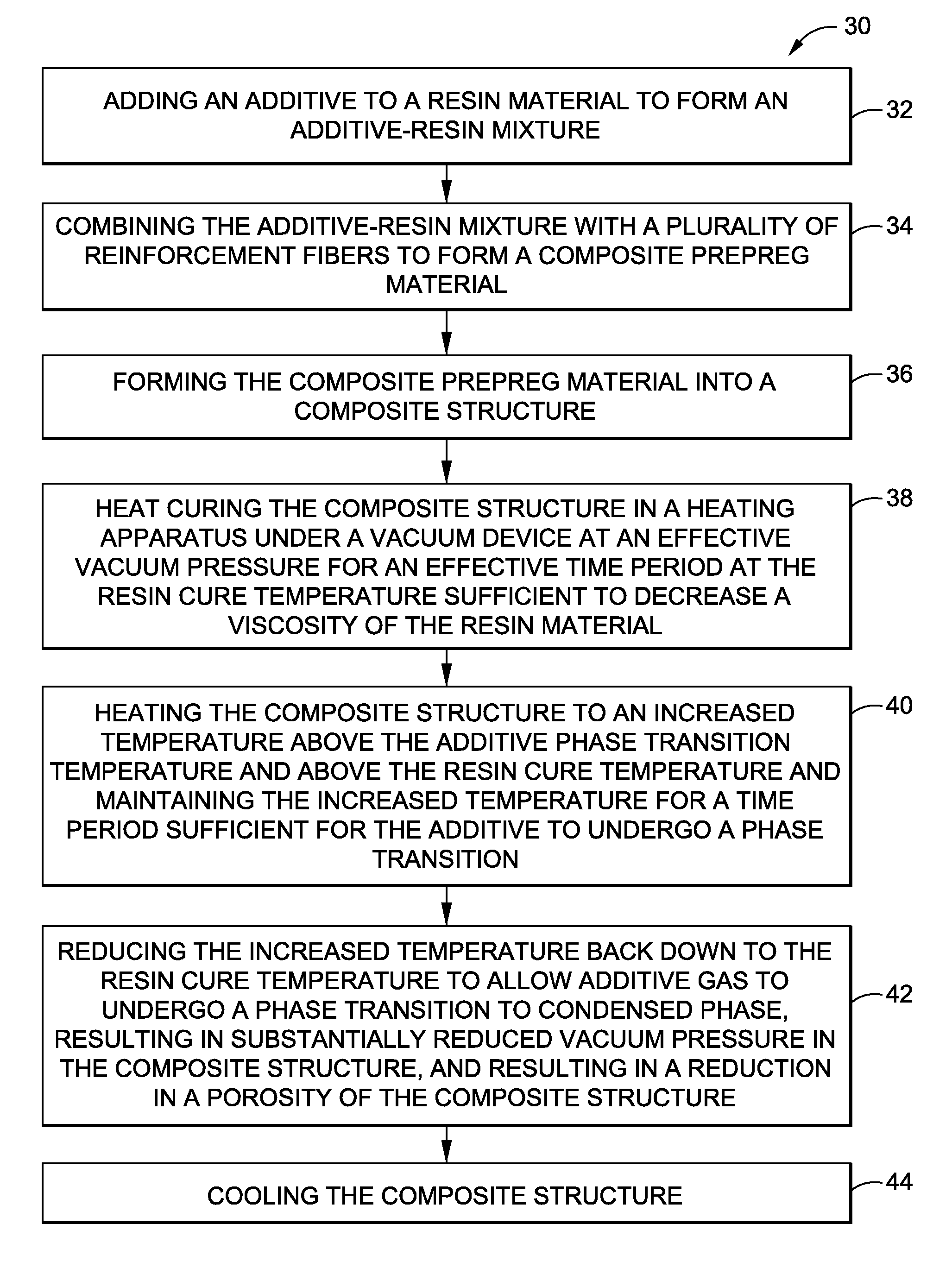
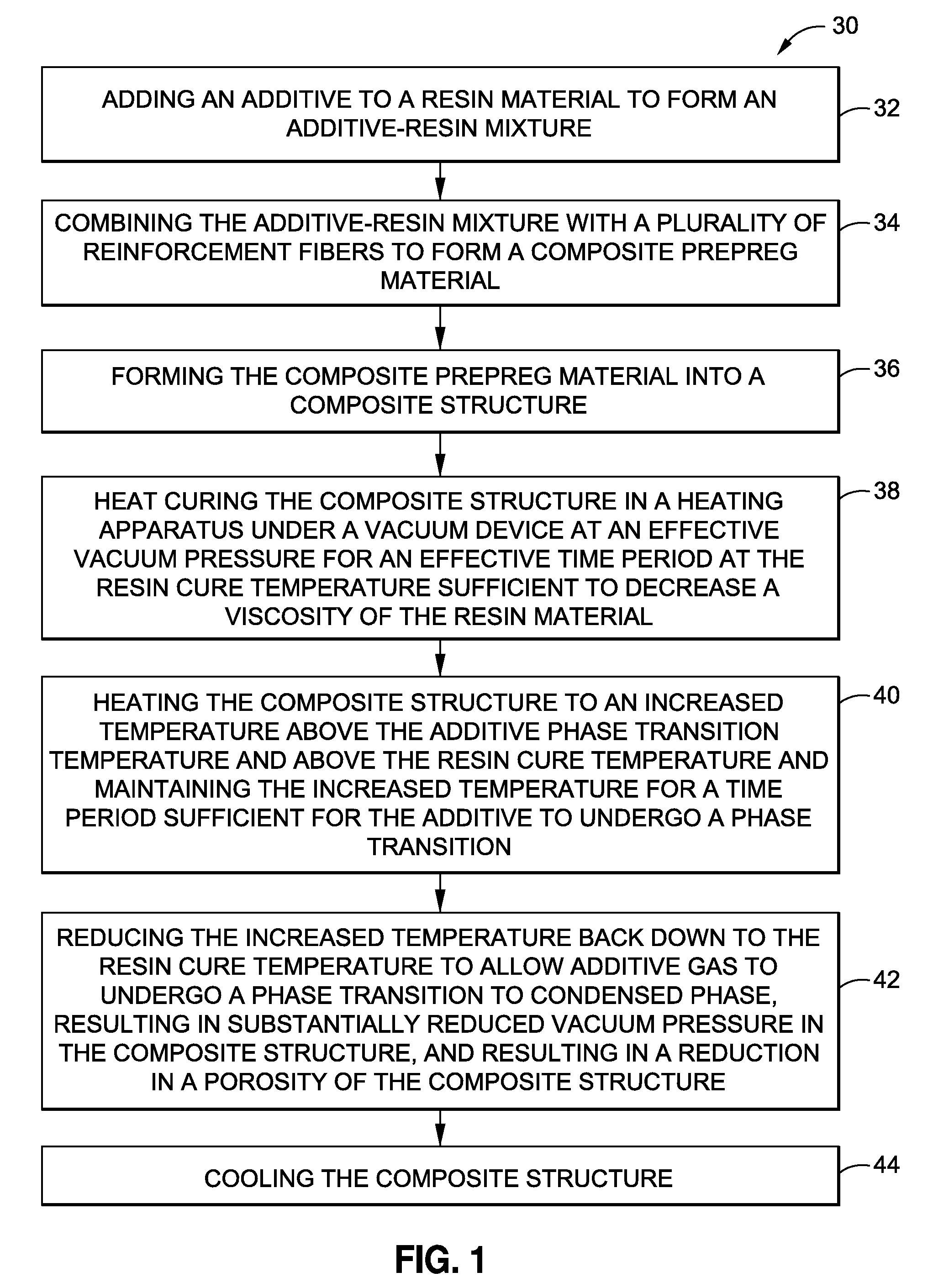
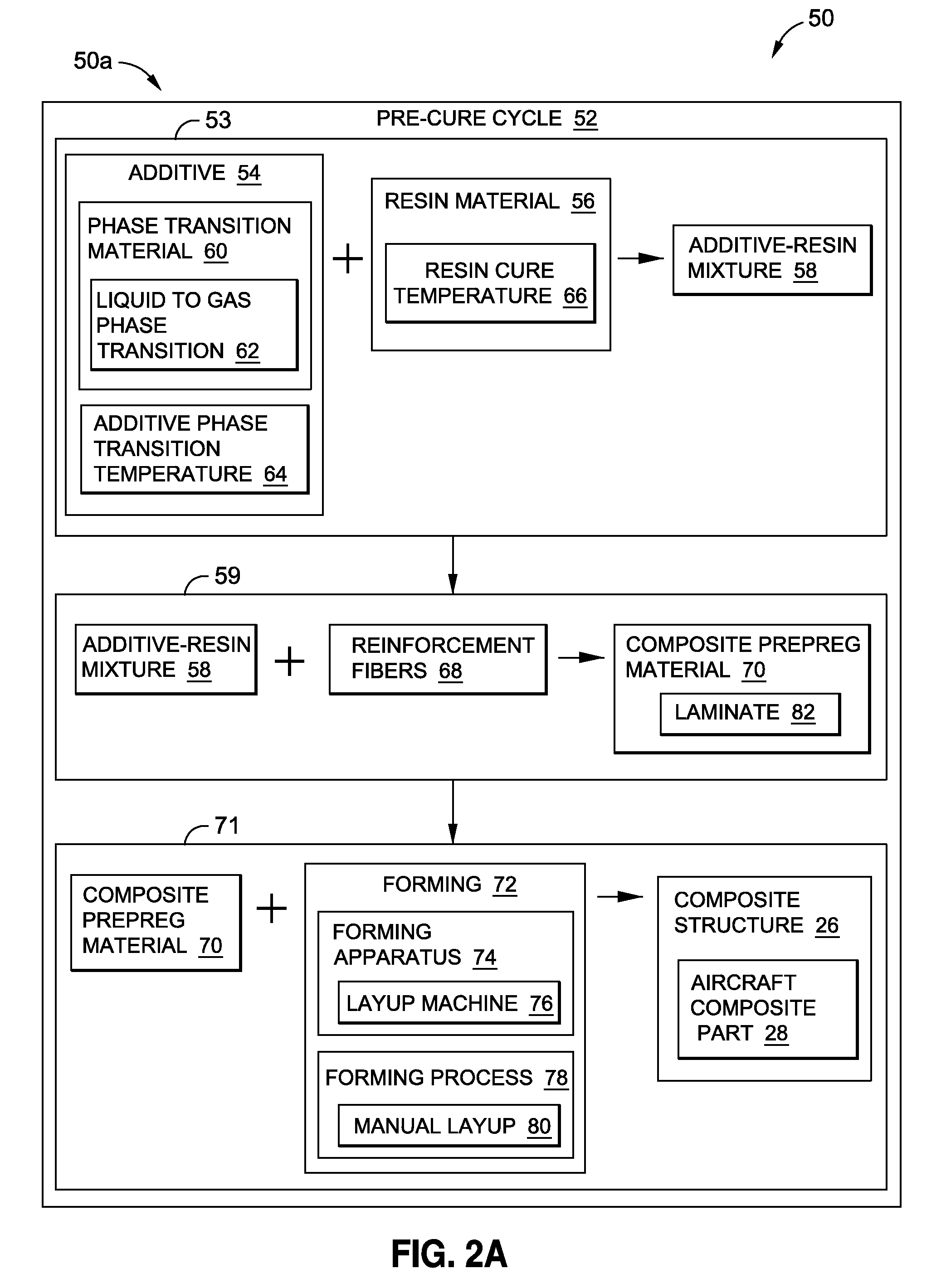
[0021]Now referring to the Figures, FIG. 1 is an illustration of a flow diagram of an exemplary embodiment of a method 30 to reduce porosity 134 (see FIG. 2B) in a composite structure 26 (see FIG. 2A). FIG. 2A is an illustration of a block diagram of one of the embodiments of a system 50 of the disclosure showing a system portion 50a in the form of a pre-cure cycle 52. FIG. 2B is an illustration of a block diagram of one of the embodiments of a system 50 of the disclosure showing a system portion 50b in th...


PUM

PropertyMeasurementUnit
temperatureaaaaaaaaaa

Abstract

In an embodiment of the disclosure, there is provided a method to reduce porosity in a composite structure. The method adds an additive to a resin material to form an additive-resin mixture. The method combines the additive-resin mixture with reinforcement fibers to form a composite prepreg material, and in turn, a composite structure. The method heat cures the composite structure in a heating apparatus under a vacuum device at the resin cure temperature, heats the composite structure to an increased temperature above the additive phase transition temperature, and maintains the increased temperature for a time period sufficient. The method reduces the increased temperature back down to the resin cure temperature to allow the additive gas to undergo a phase transition to a condense phase, resulting in a substantially reduced vacuum pressure, resulting in a reduction in a porosity of the composite structure.

Description

BACKGROUND[0001]1) Field of the Disclosure[0002]The disclosure relates generally to composite structures, and more particularly, to methods and systems for reducing porosity in composite structures, such as composite parts for aircraft.[0003]2) Description of Related Art[0004]Composite materials, such as carbon fiber-reinforced polymer (CFRP) materials, are used in the manufacture of a wide variety of structures and component parts due to their high strength and rigidity, low weight, corrosion resistance, and other favorable properties. In particular, in the manufacture of aircraft, CFRP composite structures and component parts are used in increasing quantities to form the fuselage, wings, tail sections, skin panels, and other component parts of the aircraft.[0005]During the manufacture of CFRP composite structures, unwanted voids, or empty areas, in the composite material may be created due to issues in a manufacturing process or engineering design. For example, before the cure cyc...

Claims


Application Information

Patent Timeline
Patent Type & Authority Patents(United States)
IPC IPC(8): B29C70/04
CPCY02T50/433Y02T50/43B29C70/44C08J3/20C08J5/24Y02T50/40C08J5/249C08J5/243
Inventor HUMFELD, KEITH, DANIEL
Owner THE BOEING CO
Why Eureka
Try Eureka