
Three-dimensional wind-light congregating power generating system with spherical joints

a power generation system and three-dimensional technology, applied in the direction of wind energy generation, wind motor with parallel air flow, wind motor with perpendicular air flow, etc., can solve the problems of low efficiency of conventional wind power generating system, and only absorbing less than 30% of wind energy, etc., to achieve high efficiency, reduce production cost, occupy the effect of area and production period

Active Publication Date: 2014-03-18
SHEN WEIQING
View PDF3 Cites 1 Cited by
  • Summary
  • Abstract
  • Description
  • Claims
  • Application Information

AI Technical Summary

Benefits of technology

The system achieves high efficiency in power generation from wind and solar energy, including low velocity winds and weak sunlight, with increased electric energy production through adjustable components and reduced production and transportation costs.

Problems solved by technology

However, the burning of fossil fuels often produces greenhouse gases and thus seriously affects the global climate and pollutes the environment.
But due to lacking a wind catcher, conventional wind power generating systems have a low efficiency.
However, the blades can only absorb less than 30% wind energy when wind blows the blades.
More seriously, due to the disorder of the airflow and the non-uniform action thereof on the blades, the 30% wind energy counteracts with each other and thus a lot of energy is wasted.
Therefore, conventional wind power generating systems have a low efficiency and cannot use low velocity wind to generate power.
Increasing pole height and blade length improves the power generation efficiency of a wind power generating system, but results in a bulky system and a high production cost.
Furthermore, the parts of conventional wind-solar power generating systems are generally non-detachable, which means a high occupying and transportation cost.

Method used


Image

  • Three-dimensional wind-light congregating power generating system with spherical joints
  • Three-dimensional wind-light congregating power generating system with spherical joints
  • Three-dimensional wind-light congregating power generating system with spherical joints

Examples


Embodiment Construction

[0038]For further illustrating the invention, experiments detailing a socket joint-typed three-dimensional wind-solar congregating power generating system are described below. It should be noted that the following examples are intended to describe and not to limit the invention. Technical terms involved in the invention refer to any practicable means, for example, “connection”refers to a direct connection between two components or an indirect connection via a connection device.

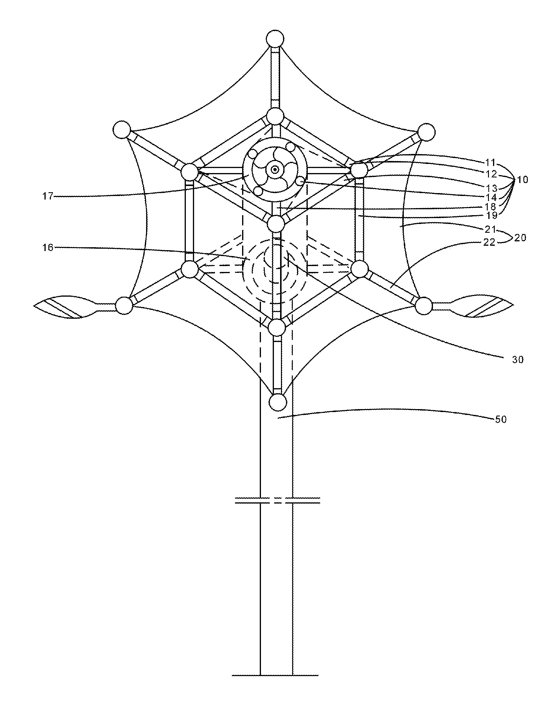
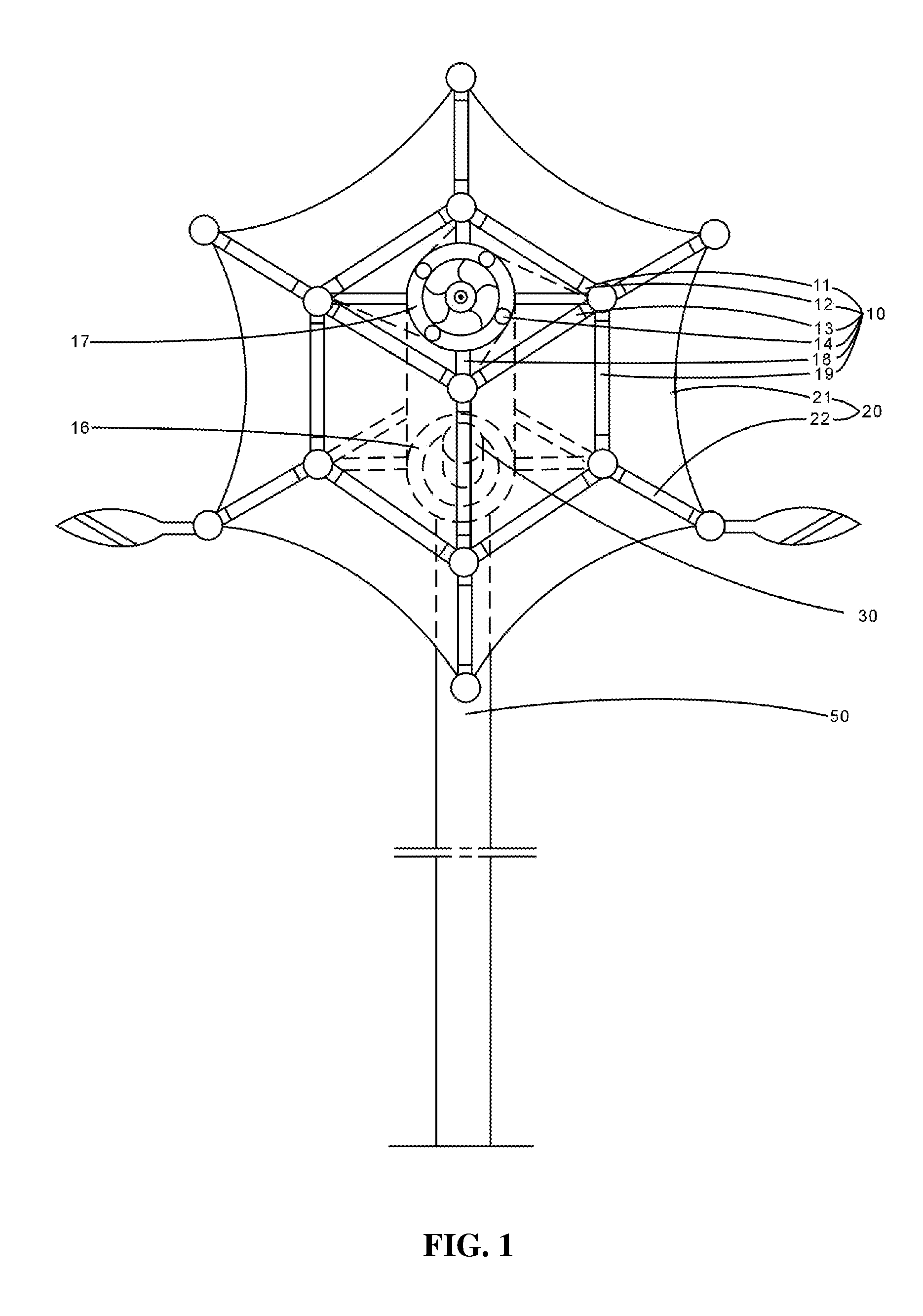
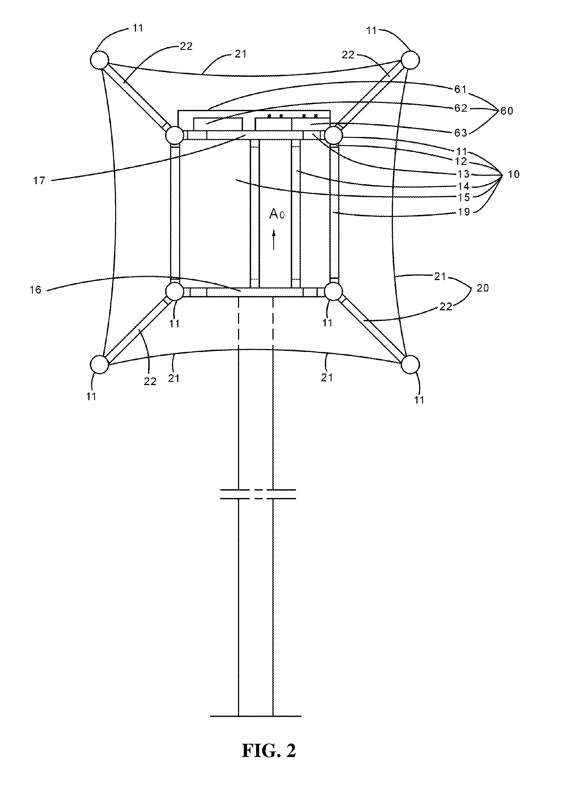
[0039]As shown in FIGS. 1-3 and 5, a socket joint-typed three-dimensional wind-solar congregating power generating system comprises a wind-solar aggregator 10, a vertical axis wind power generator 30, and a wind-solar catcher 20. FIG. 6 shows another socket joint-typed three-dimensional wind-solar congregating power generating system comprises a plurality of wind-solar aggregators 10, a plurality of vertical axis wind power generators 30, and a wind-solar catcher 20.

[0040]As shown in FIGS. 1-3 and 5, the wind-...


PUM


Abstract

A three-dimensional wind-light congregating power generating system with spherical joints includes a spherical joint wind-light congregating device (10), a spherical joint wind-light trapping device (20), both of which are assembled through spherical joints, and a vertical axis wind generator (30), wherein the profile of the spherical joint wind-light congregating device (10) is the shape of rectangular paralleling and comprises four wind lateral guiding boards (15) equally spaced around a center, a gradually narrowing wind inlet passage (150) is formed between adjacent wind lateral guiding boards (15), and the wind inlets of the wind inlet passages (150) are located respectively at the four sides of the spherical joint wind-light congregating device (10); the spherical joint wind-light trapping device (20) comprises wind-light trapping rods (22) and wind-light trapping films (21) for absorbing solar energy; the vertical axis wind generator (30) is mounted in the center of the spherical joint wind-light congregating device (10). The present power generating system applies an assembled structure with spherical joints, the components of the system can be produced in standardization and be assembled together by simple tools, and a plurality of miniwatt power generating systems can be assembled to a high power generating system; the power generating system can generate electricity efficiently all day even in the condition of gentle breeze and weak light.

Description

FIELD OF THE INVENTION[0001]The invention relates to a wind power generating system and more particularly, to a socket joint-typed three-dimensional wind-solar congregating power generating system.BACKGROUND OF THE INVENTION[0002]Conventional methods for obtaining electric energy include the burning fossil fuels. However, the burning of fossil fuels often produces greenhouse gases and thus seriously affects the global climate and pollutes the environment. Wind power generation solves the above-mentioned problems and saves non-renewable resources, and in contrast to nuclear power generation, hydropower generation, and thermal power generation, it is very economic in construction cost and occupancy area.[0003]The global wind energy reserves are very large and theoretically, 1% of the wind energy reserves can meet the demand of human beings. But due to lacking a wind catcher, conventional wind power generating systems have a low efficiency.[0004]When wind drives blades to rotate, power...

Claims


Application Information

Patent Timeline
Patent Type & Authority Patents(United States)
IPC IPC(8): F03D9/00H02J7/34
CPCY02E10/74Y02E10/72F03D3/0463F03D1/04F03D3/049F24J2/04F05B2240/13Y10T307/658Y02P90/50F24S10/00F03D9/007F03D3/0427F03D9/25F03D9/11F03D13/20H02S10/12Y02E10/50Y02P70/50Y02P80/20Y02E70/30
Inventor SHEN, WEIQING
Owner SHEN WEIQING
Learn More