Method of use for a multipole detector for a transmission electron microscope

Active Publication Date: 2014-04-08
FEI COMPANY
View PDF42 Cites 2 Cited by
  • Summary
  • Abstract
  • Description
  • Claims
  • Application Information

AI Technical Summary

Benefits of technology

[0037]It is noted that, although in this embodiment the distortions of the lens(es) between object plane and pattern plane cannot be corrected, the lenses closer to the image plane typically introduce more distortions than the lens closer to the object. This is caused by the progressively larger magnification from the o

Problems solved by technology

As known to the person skilled in the art a projection system not only forms an image of the sample to the image plane, but also introduces aberrations and distortions.
In this context aberrations are the errors resulting in a point to be imaged as a blur, and distortions are those errors that result in a warp of the image.
Distortions of the image may limit the performance of e.g. a TEM.
As in some images the feature may be in the centre of the image, while in other images the feature may be removed from the centre, the displacement is not constant, resulting in a blurring of the feature in the 3D reconstruction.
This is aggravated by the fact that the magnification used in tomography is often relative

Method used


Image

  • Method of use for a multipole detector for a transmission electron microscope
  • Method of use for a multipole detector for a transmission electron microscope
  • Method of use for a multipole detector for a transmission electron microscope

Examples


Embodiment Construction

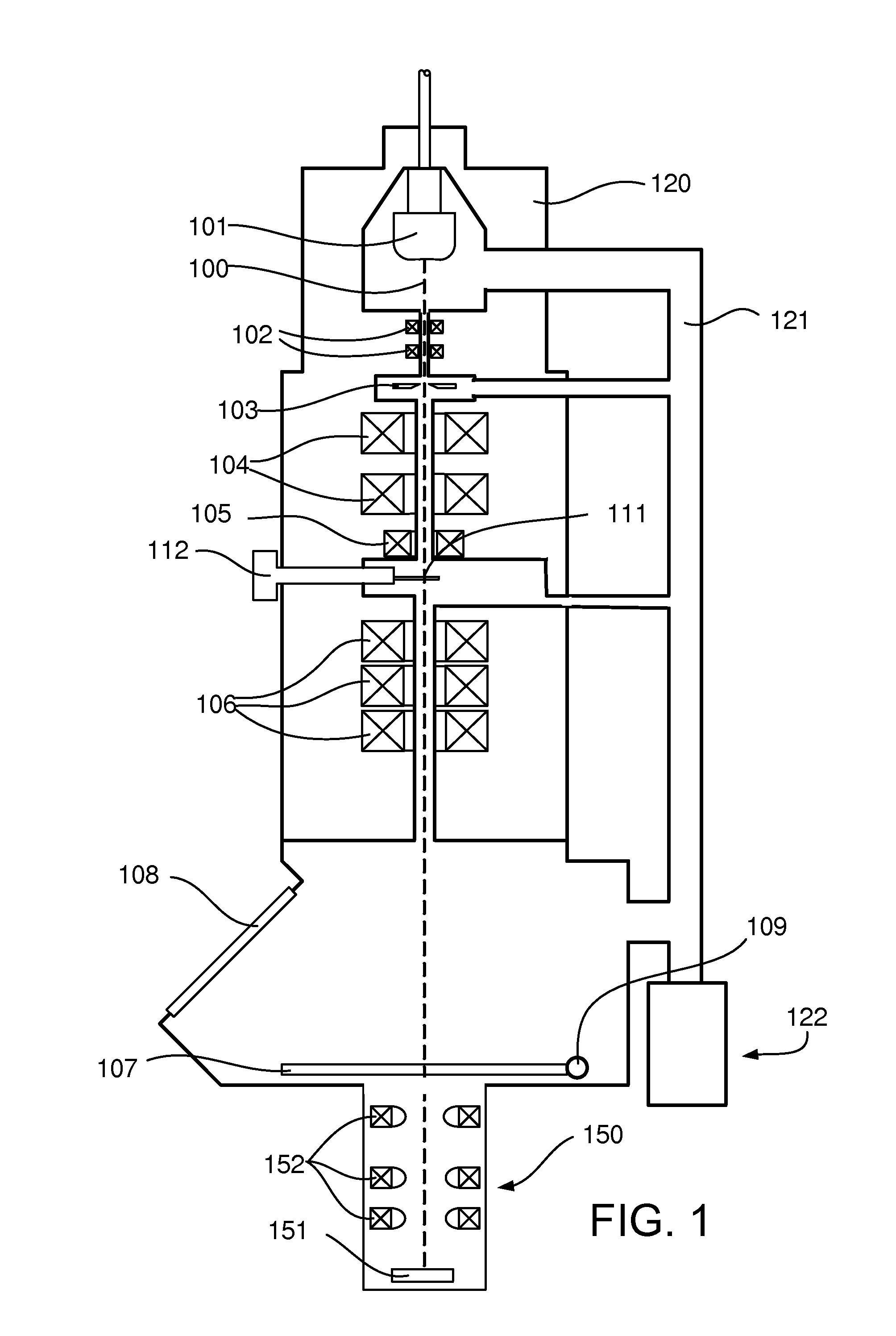
[0056]FIG. 1 schematically shows the apparatus according to the invention. It shows a TEM, comprising a vacuum housing 120 evacuated via tube 121 by a vacuum pump 122. A particle source in the form of an electron gun 101 produces a beam of electrons along a particle-optical axis 100. Deflectors 102 centre the beam of particles on beam limiting aperture 103. The beam then passes through a condenser system comprising two lenses 104.

[0057]A sample 111 is held by a manipulator 112, positioning the sample in the object plane of the objective lens 105. The sample is imaged by a projection system comprising lenses 106 onto fluorescent screen 107, and can be viewed through a window 108. The fluorescent screen 107 is connected to a hinge 109 and can be retracted / folded away, so that the image made by the projection system is imaged on detector 150. It is noted that the projection system may need to be re-focused so as to form the image on the detector 150 instead of on the fluorescent screen...


PUM


Abstract

The invention relates to a method for correcting distortions introduced by the projection system (106) of a TEM. As known to the person skilled in the art distortions may limit the resolution of a TEM, especially when making a 3D reconstruction of a feature using tomography. Also when using strain analysis in a TEM the distortions may limit the detection of strain.
To this end the invention discloses a detector equipped with multipoles (152), the multipoles warping the image of the TEM in such a way that distortions introduced by the projection system are counteracted. The detector may further include a CCD or a fluorescent screen (151) for detecting the electrons.

Description

TECHNICAL FIELD[0001]The invention relates to a method for correcting distortions in a particle-optical apparatus, the particle-optical apparatus comprising:[0002]a particle source for producing a beam of particles,[0003]an object plane on which an object to be imaged may be placed,[0004]a condenser system for illuminating the object with the beam of particles,[0005]a projection system for forming an enlarged image of the object by imaging particles transmitted through the object on an image plane, the projection system introducing distortions, and[0006]a detector for detecting the enlarged image,the method comprising:[0007]forming an image in which the distortions are at least partially corrected.[0008]The invention further relates to a method of determining the distortions.BACKGROUND[0009]This method is disclosed in “Calibration of projector lens distortions for quantitative high-resolution TEM”, F. Hue et al., Microsc. Microanal. 11 (supplement 2), 2005, pages 552-553, (DOI:10.10...

Claims


Application Information

Patent Timeline
IPC IPC(8): G01N23/00
CPCH01J37/263H01J2237/2823H01J37/153H01J2237/1534
Inventor TIEMEIJER, PETER CHRISTIAANLUECKEN, UWEDE JONG, ALAN FRANKSLINGERLAND, HENDRIK NICOLAAS
Owner FEI COMPANY
Why Eureka
Try Eureka