Valve gear of engine

a valve gear and engine technology, applied in the direction of mechanical control devices, process and machine control, instruments, etc., can solve the problems of cam action not being reliably transmitted to the intake valve or the exhaust valve during a high-speed operation, the mass of the rocker arm is significantly reduced, and the production cost is low. , the effect of reducing power loss

Inactive Publication Date: 2014-05-06
YAMAHA MOTOR CO LTD
View PDF14 Cites 19 Cited by
  • Summary
  • Abstract
  • Description
  • Claims
  • Application Information

AI Technical Summary

Benefits of technology

[0015]In order to solve or lessen the effects of the above-mentioned problems, preferred embodiments of the present invention provide a valve drive system of an engine in which the mass of a rocker arm is significantly reduced. Additionally, preferred embodiments of the present invention provide a valve drive system

Problems solved by technology

Therefore, these valve drive systems increase in the mass of the rocker arm.
Additionally, the rocker arm has a complex structure, and hence has a possibility that a portion of the rocker arm may have a low rigidity.
If the rocker arm is great in mass and is low in rigidity, a cam action cannot be reliably transmitted to the intake valve or the exhaust valve during a high-speed operation.
In this case, the opening/closing timing and the amount of valve lift may become inaccurate, thus resulting in damage to the valve drive system.
H2-43004 and

Method used


Image

  • Valve gear of engine
  • Valve gear of engine
  • Valve gear of engine

Examples


first preferred embodiment

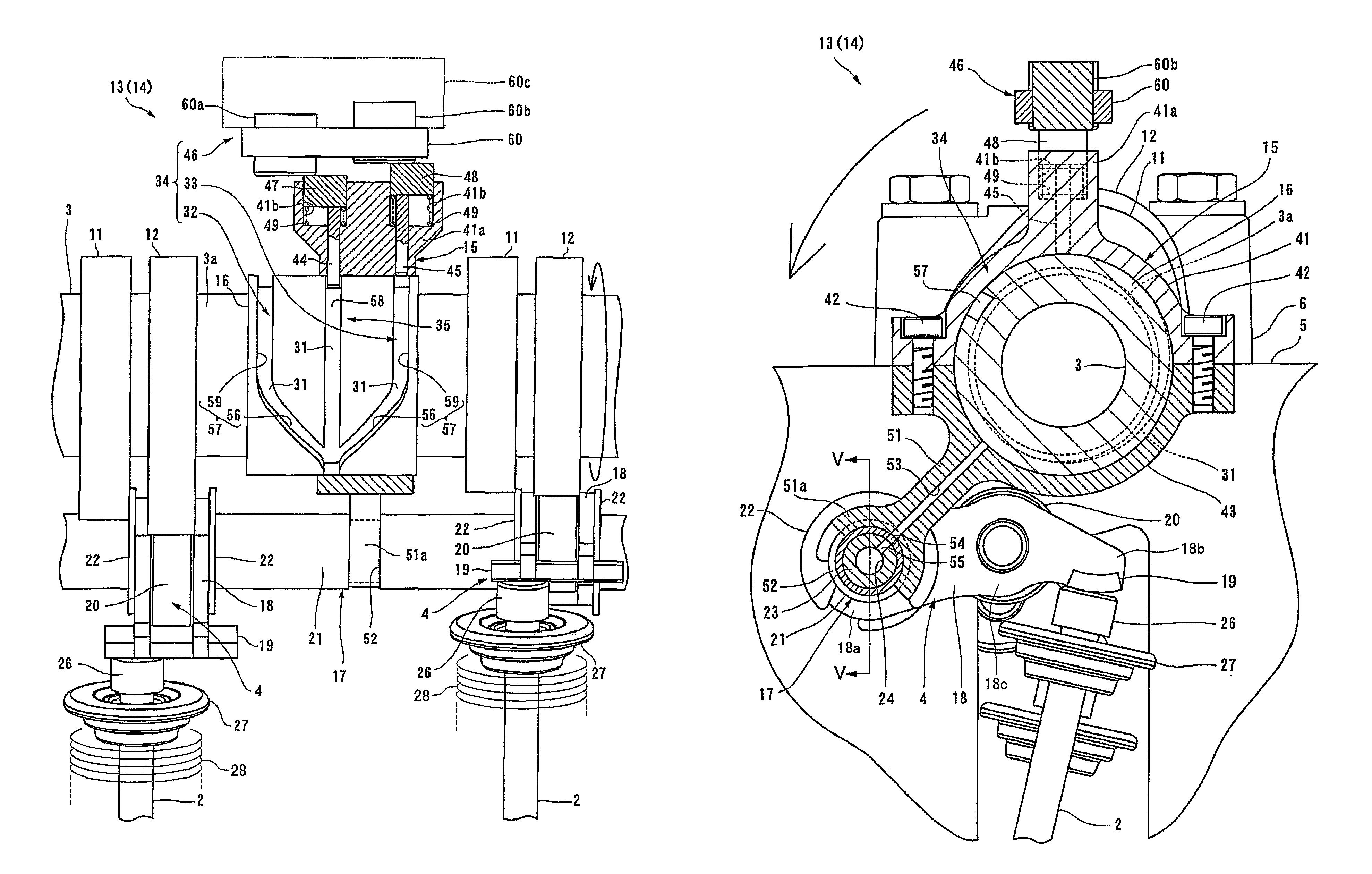
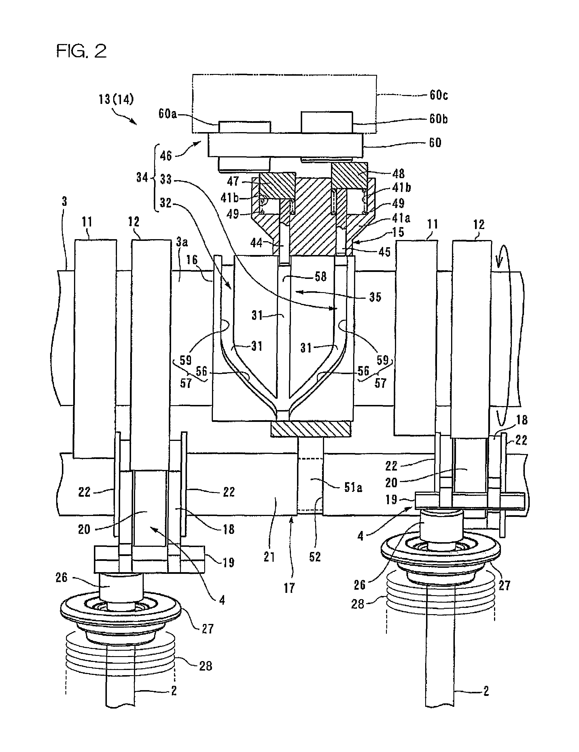
[0049]A first preferred embodiment of a valve drive system of an engine according to the present invention will be hereinafter described in detail with reference to FIG. 1 to FIG. 9B. The present preferred embodiment is one example in which the present invention is preferably applied to an in-line four-cylinder engine, for example.

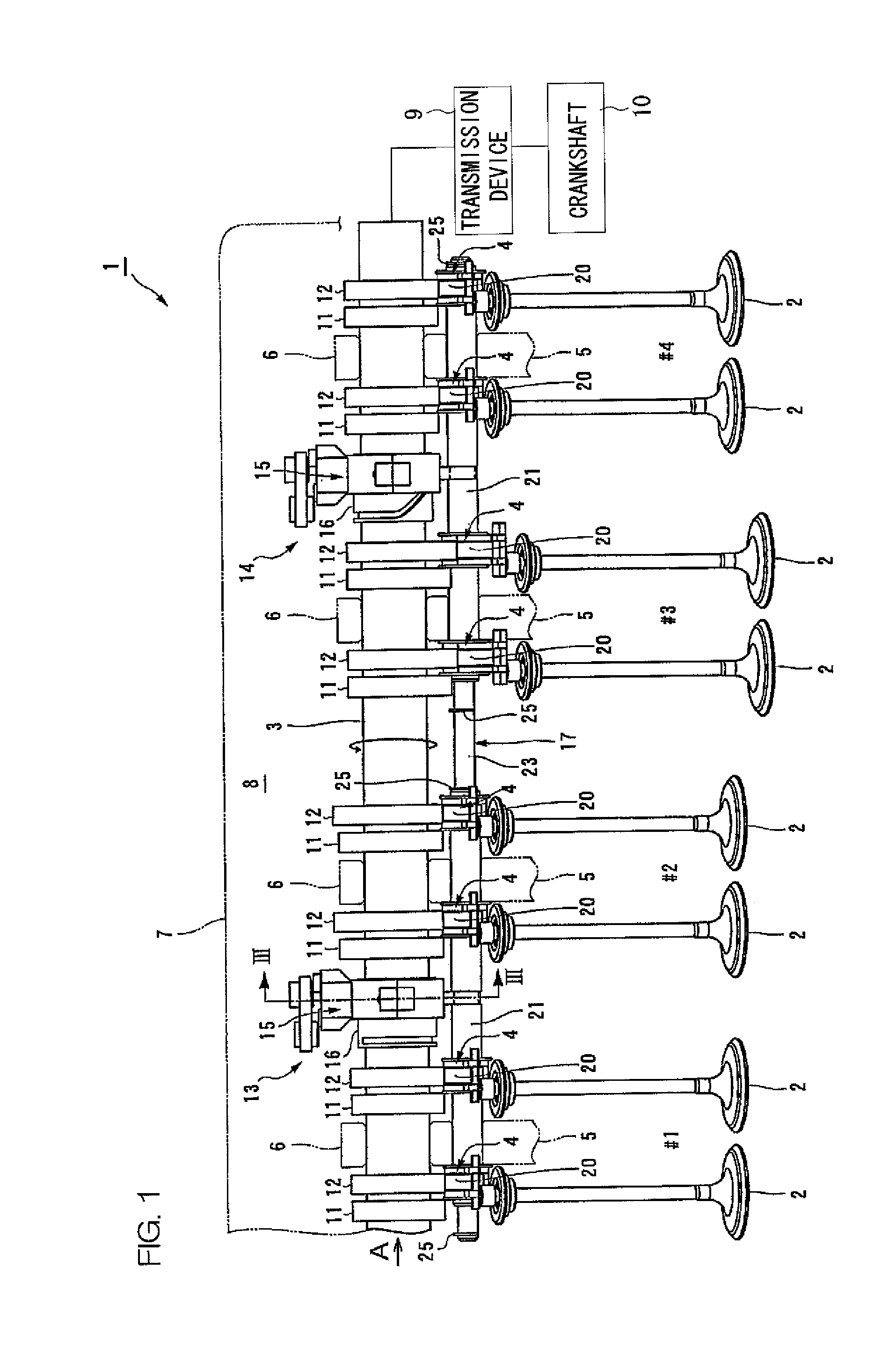
[0050]A valve drive system 1 of an engine shown in FIG. 1 is arranged so as to drive valves 2, two of which are preferably provided for each cylinder, for example, via a camshaft 3 and a rocker arm 4. The valve 2 is an intake valve or an exhaust valve. The valve drive system 1 is applicable to an engine that includes an intake camshaft and an exhaust camshaft. The valve drive system 1 is applicable also to an engine that includes only one camshaft. Therefore, in a description of the present preferred embodiment, no distinction is drawn between members of the intake system and members of the exhaust system.

[0051]The engine to which the valve drive system 1 ...

second preferred embodiment

[0124]The valve drive system of the present invention can be used to perform switching an active cam for an operating state and a dormant cam for a dormant state. A preferred embodiment including this arrangement will be described in detail with reference to FIGS. 10A and 10B and FIGS. 11A and 11B. In these figures, the same reference numeral is given to the same or equivalent member as in FIG. 1 to FIG. 9B, and a detailed description of the same or equivalent member is omitted.

[0125]The valve drive system 61 shown in FIGS. 10A and 10B preferably includes a drive unit 13 that performs switching between cams 62 for the second cylinder #2 and a drive unit 14 that performs switching between cams 62 for the third cylinder #3. The cams 62 for the second and third cylinders #2 and #3 include active cams 63 and dormant cams 64, respectively.

[0126]With respect to the first cylinder #1 and the fourth cylinder #4, only the active cams 65 are provided, and the dormant cams are not provided. Th...

third preferred embodiment

[0139]The valve drive system of the present invention can be used in a V-type eight-cylinder engine, for example. A preferred embodiment of the valve drive system applicable to the V-type eight-cylinder engine will be described in detail with reference to FIGS. 12A to 12C and FIGS. 13A and 13B. In FIGS. 13A and 13B, the same reference numeral is given to the same or equivalent member as in FIG. 1 to FIG. 9B, and a detailed description of the same or equivalent member is omitted.

[0140]The valve drive system 81 (see FIGS. 13A and 13B) according to the present preferred embodiment is arranged so as to perform switching between operation modes of the V-type eight-cylinder engine. One operation mode is a mode in which the V-type eight-cylinder engine is used as a V-type eight-cylinder engine. Another operation mode is a mode in which the V-type eight-cylinder engine is used substantially as a V-type four-cylinder engine by decreasing the number of driven cylinders. The V-type eight-cylin...


PUM


Abstract

A valve drive system of an engine includes a camshaft that is supported by a cylinder head of the engine and on which a plurality of cams having different valve lift characteristics are arranged at predetermined intervals, a rocker shaft that is supported by the cylinder head so as to be parallel or substantially parallel to the camshaft, and a rocker arm that is swingably supported by the rocker shaft. The rocker arm is arranged between one of the cams and an intake valve or an exhaust valve and is arranged so as to be movable in an axial direction of the rocker shaft. A presser of the rocker arm that presses the intake valve or the exhaust valve extends in the axial direction and has a length greater than an interval between the cams. The valve drive system includes a drive unit that moves the rocker arm toward one side or toward an opposite side in the axial direction by the interval between the cams.

Description

BACKGROUND OF THE INVENTION[0001]1. Field of the Invention[0002]The present invention relates to a valve gear or valve drive system of an engine, and particularly, to a valve drive system that includes a switching mechanism that performs switching between a plurality of cams having different valve lift characteristics.[0003]2. Description of the Related Art[0004]Conventional techniques for a valve drive system of an engine are disclosed in, for example, Japanese Published Examined Patent Application No. H2-43004, Japanese Patent No. 3365805, and Japanese Translation of International Application No. 2006-520869.[0005]A valve drive system disclosed in Japanese Published Examined Patent Application No. H2-43004 includes a low-speed rocker arm that is pressed by a low-speed cam that is used for a low speed, a high-speed rocker arm that is pressed by a high-speed cam that is used for a high speed, and a switching mechanism that performs switching between the cams to be used. In this valv...

Claims


Application Information

Patent Timeline
IPC IPC(8): F01L1/18
CPCF01L1/047F01L13/0042F01L1/18F01L2013/0052Y10T74/2107Y10T74/20882
Inventor KAMICHIKA, TAKUROU
Owner YAMAHA MOTOR CO LTD
Why Eureka
Try Eureka