Planar-waveguide Bragg gratings in curved waveguides

a bragging and waveguide technology, applied in the direction of optical waveguide light guides, instruments, optical elements, etc., can solve the problems of increased overall system size, increased insertion loss, and limited fiber location accuracy, so as to reduce fabrication requirements, reduce insertion loss, and increase the grating period

Inactive Publication Date: 2014-05-20
THE UNITED STATES OF AMERICA AS REPRESENTED BY THE SECRETARY OF THE NAVY
View PDF11 Cites 67 Cited by
  • Summary
  • Abstract
  • Description
  • Claims
  • Application Information

AI Technical Summary

Benefits of technology

[0006]In one embodiment, a method for forming planar-waveguide Bragg grating in a curved waveguide comprises: forming a long chirped planar-waveguide Bragg grating in an Archimedes' spiral such that a long length of the waveguide can fit in a small chip area for single mask photolithography fabrication where the grating is formed in the curved waveguide; using periodic width modulation to form the planar-waveguide Bragg grating on the curved with modulation periods equal to RinΛ / (Rin+W / 2) and RoutΛ / (Rout−W / 2) for the inner and outer edge of the curve waveguide, where Rin and Rout are the inner and outer radius, Λ is modulation period for Bragg condition, and W is the width of the waveguide and where the formation of the periodic width modulation occurs during the etching of the waveguide core; using rectangular width modulation to create Bragg gratings with a higher order than 1st order to allow a larger grating period and larger modulation depth, and therefore relax fabrication requirements; and using waveguide width tapering while keeping the width modulation period constant to introduce chirp to the planar-waveguide Bragg grating where the index of refraction is a function of waveguide width, by applying a specific width tapering such that desired arbitrary chirp profile can be created for the planar-waveguide Bragg grating.

Problems solved by technology

The accuracy of the fiber location is limited by the motion stage encoder moving the fiber.
Having a long length of DCF in a system not only increases the overall system size, but also introduces extra insertion loss.

Method used


Image

  • Planar-waveguide Bragg gratings in curved waveguides
  • Planar-waveguide Bragg gratings in curved waveguides
  • Planar-waveguide Bragg gratings in curved waveguides

Examples


Embodiment Construction

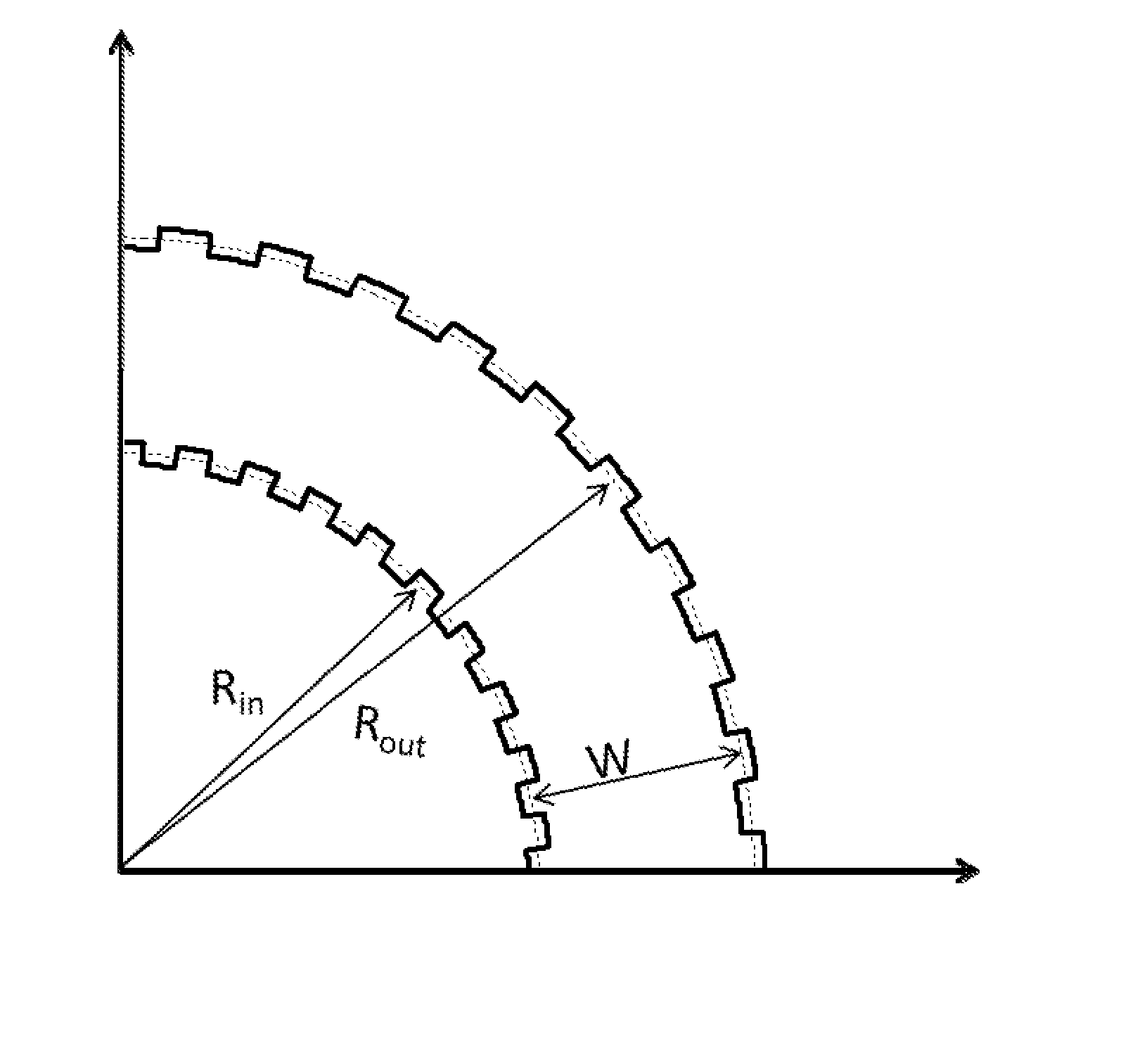
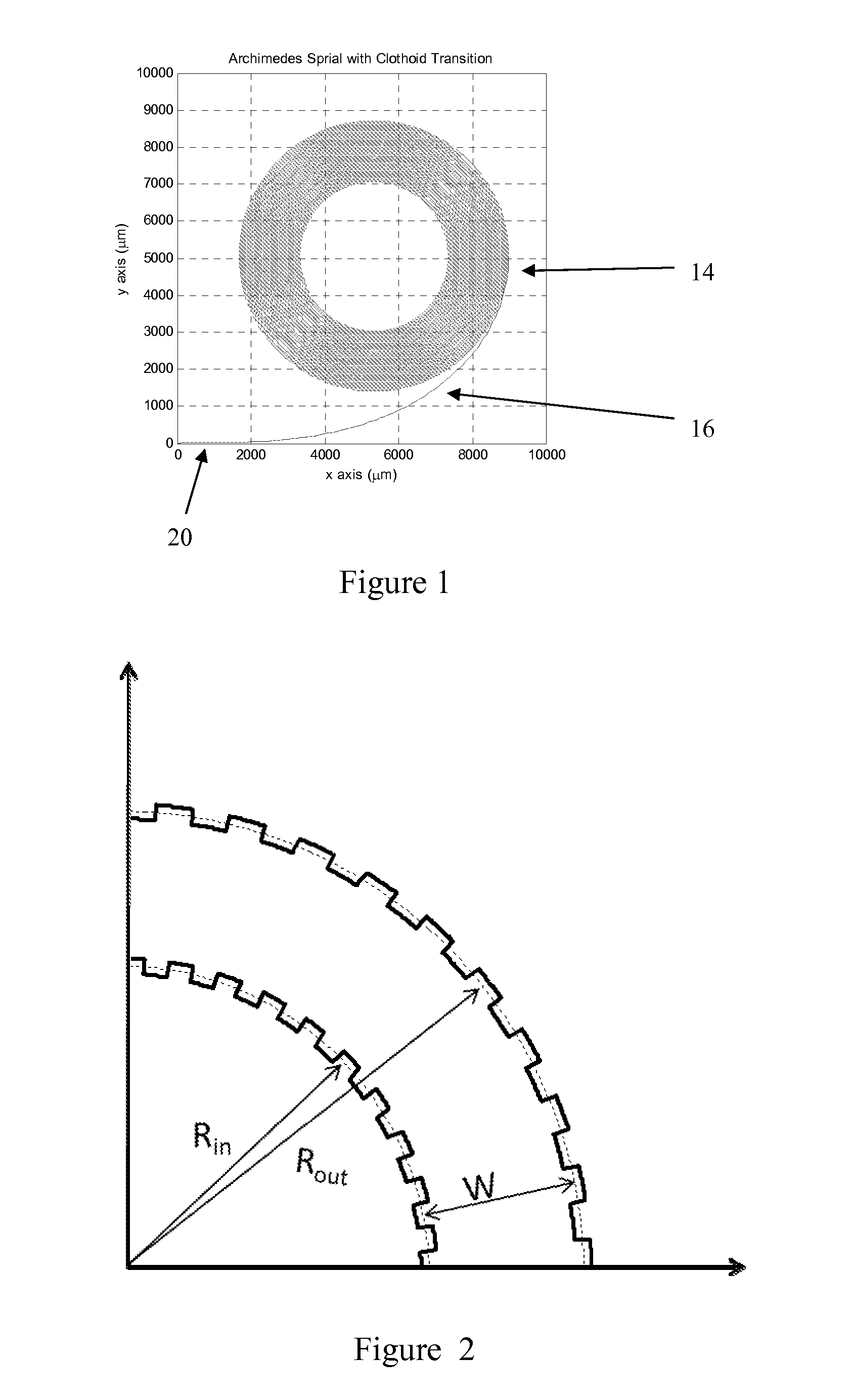
[0016]The present invention is a long chirped planar-waveguide Bragg grating with high dispersion that could be used for a variety of applications such as routing, filtering, dispersion compensation and optical time-stretch processing. The present invention provides planar-waveguide Bragg gratings that can provide customized dispersion properties for various applications.

[0017]It is important for signal processing applications to have large dispersion (long grating) and low optical loss gratings. With the present invention, the long chirped planar-waveguide Bragg grating with Archimedes' spiral geometry can be fit in a small area (for example, ˜1 m can be realized in an area of 1 cm2). The ability to form the grating in such a small area enables the use of a single photolithography mask. Therefore the large physical translation associated with long CFBG fabrication methods is avoided, and the associated specialized fabrication equipment is replaced by standard photolithography equip...


PUM

PropertyMeasurementUnit
grating reflectivityaaaaaaaaaa
areaaaaaaaaaaa
insertion lossaaaaaaaaaa

Abstract

A method for forming planar-waveguide Bragg grating in a curved waveguide comprises: forming a long chirped planar-waveguide Bragg grating in an Archimedes' spiral such that a long length of the waveguide can fit in a small chip area where the grating is formed in the curved waveguide; using periodic width modulation to form the planar-waveguide Bragg grating on the curved waveguide, and where the formation of the periodic width modulation occurs during the etching of the waveguide core; using rectangular width modulation to create Bragg gratings with a higher order than 1st order to allow a larger grating period and larger modulation depth, using waveguide width tapering while keeping the width modulation period constant to introduce chirp to the planar-waveguide Bragg grating where the index of refraction is a function of waveguide width, by applying a specific width tapering to create a desired arbitrary chirp profile.

Description

FEDERALLY-SPONSORED RESEARCH AND DEVELOPMENT[0001]This invention (Navy Case No. 101,402) is assigned to the United States Government and is available for licensing for commercial purposes. Licensing and technical inquires may be directed to the Office of Research and Technical Applications, Space and Naval Warfare Systems Center, Pacific, Code 72120, San Diego, Calif. 92152; voice (619) 553-2778; email T2@spawar.navy.mil.BACKGROUND OF THE INVENTION[0002]This invention disclosure describes a method for realizing a long chirped planar-waveguide Bragg grating with Archemedes' spiral geometry that can fit in a small area (˜1 m can be realized in an area of 1 cm2) and provide large dispersion. The ability to form the grating in such a small area enables fabrication with only a single photolithography mask. Therefore the large physical translation associated with long CFBG fabrication methods is avoided, and the associated specialized fabrication equipment is replaced by standard photolit...

Claims


Application Information

Patent Timeline
Patent Type & Authority Patents(United States)
IPC IPC(8): G02B6/34G02F1/295G02B6/10
CPCG02B6/12007G02B6/136G02B6/124G02F1/295G02B6/34G02B6/10
Inventor LIN, CHUNYANJACOBS, EVERETT W.ADLEMAN, JAMES R.RODGERS, JOHN SCOTT
Owner THE UNITED STATES OF AMERICA AS REPRESENTED BY THE SECRETARY OF THE NAVY
Why Eureka
Try Eureka