
RF cavity fabrication method including adherence of superconductor-coated tiles

a superconductor-coated, rf cavity technology, applied in the direction of accelerators, resonators, electrical devices, etc., can solve the problems of complex, bulky, expensive liquid-helium-based cooling systems, etc., and achieve the effect of convenient, convenient and economical operation

Inactive Publication Date: 2014-05-20
THE UNITED STATES OF AMERICA AS REPRESENTED BY THE SECRETARY OF THE NAVY
View PDF2 Cites 7 Cited by
  • Summary
  • Abstract
  • Description
  • Claims
  • Application Information

AI Technical Summary

Benefits of technology

The MgB2-based RF cavities offer superior performance and lower manufacturing and operational costs, with potential for higher acceleration fields and reduced cooling system complexity, utilizing gaseous helium cooling and flexible tile design to overcome brittleness and shape constraints.

Problems solved by technology

Factors such as residual local surface imperfections and field transients can lead to localized heating that can quickly spread throughout the cavity and result in a breakdown.
However, as previously noted herein, the low critical temperature Tc of niobium mandates operation in the temperature range T=2-4 K. This low operation temperature requires a complex, bulky and expensive liquid-helium-based cooling system.
Furthermore, the low thermodynamic critical field (HC=0.2 Tesla) of niobium imposes constraints on practicable cavity shapes and on maximally achievable accelerating electric field EACC.

Method used


Image

  • RF cavity fabrication method including adherence of superconductor-coated tiles
  • RF cavity fabrication method including adherence of superconductor-coated tiles
  • RF cavity fabrication method including adherence of superconductor-coated tiles

Examples


Embodiment Construction

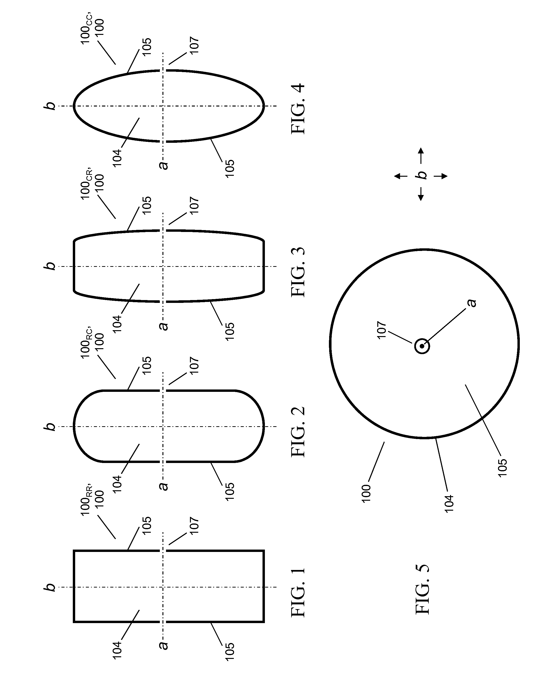
[0053]Referring now to FIG. 1 through FIG. 5, cavity preforms 100 that are suitable for inventive practice are typically characterized by conventional “pillbox” shapes. The terms “cavity preform” and “cold cavity” are used synonymously herein to refer to the “superconductor-less” frame of an RF cavity, i.e., the basic RF cavity structure, absent superconductor material. A cavity preform is typically a rigid, hollow, “walling” structure, and is typically made of a metallic (metal or metal alloy) material, although it could be made of another (e.g., ceramic or composite) suitable material. The term “pillbox” is broadly used herein to describe a shape that is cylindrical or generally cylindrical.

[0054]As depicted in FIG. 1 through FIG. 4, pillbox cavity preform 100 is characterized by lateral symmetry, straight and / or curved, with respect to its geometric planar bisector b, with respect to which its geometric axis a is perpendicular. As further depicted in FIG. 1 through FIG. 4, a pill...


PUM


Abstract

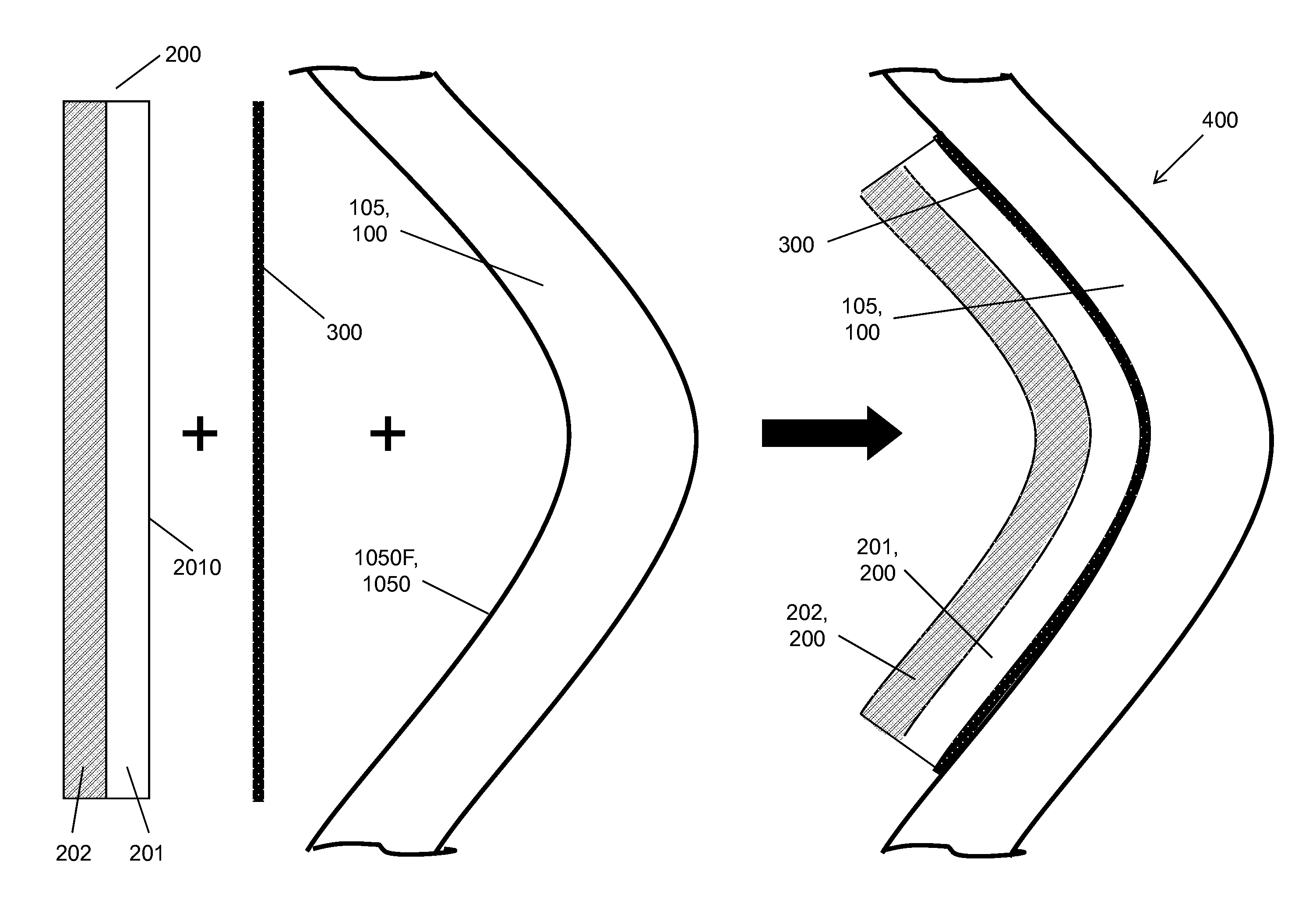
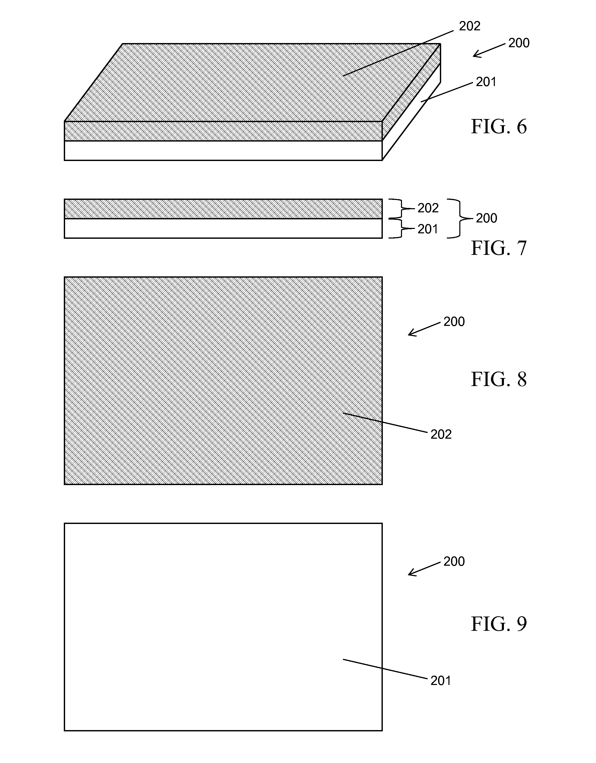
As typically embodied, the present invention's RF cavity device comprises a rigid frame and plural flexible tiles. The frame includes walls of at least substantially uniform thicknesses that describe a hollow pillbox shape. The tiles are at least approximately equally thick, each tile being of at least substantially uniform thickness. Each tile includes a flexible metallic substrate and an HTS coating atop the substrate. The tiles are attached via their corresponding substrates to the inside wall surfaces of the frame so that their corresponding HTS coatings are interiorly exposed. The attached tiles flexibly conform to curved surface areas, are snugly set with narrow seams therebetween, and cover at least approximately the entirety of the frame's inside wall surfaces. A filler material is applied to the seams. The resultant tile configuration is characterized by at least approximate levelness of the exposed HTS coating surfaces and the filled seams.

Description

STATEMENT OF GOVERNMENT INTEREST[0001]The invention described herein may be manufactured and used by or for the Government of the United States of America for governmental purposes without payment of any royalties thereon or therefor.BACKGROUND OF THE INVENTION[0002]The present invention relates to charged particle accelerator devices, more particularly to resonant cavity structures used in particle accelerator devices for sustaining high acceleration fields.[0003]Particle accelerator devices such as high-energy accelerators and free electron lasers (FEL) are designed to accelerate charged atomic particles such as ions, protons, or electrons. Acceleration of a beam of charged particles is traditionally accomplished using a synchronized linear radio frequency (RF) cavity array. Each cavity in such a linear array sustains a high-intensity RF radiation field in order to generate a high acceleration field. A synchronized acceleration electric field EACC is applied by each cavity along t...

Claims


Application Information

Patent Timeline
Patent Type & Authority Patents(United States)
IPC IPC(8): H01P7/06H05H7/20H01L39/14H01P11/00H01P1/203H01L39/00H10N60/00H10N60/20
CPCH01P7/06H01L39/24H05H7/20H01P11/008H10N60/01
Inventor AGASSI, YEHOSHUA DANOATES, DANIEL E.
Owner THE UNITED STATES OF AMERICA AS REPRESENTED BY THE SECRETARY OF THE NAVY
Learn More