Peri-vascular tissue ablation catheter with support structures

a technology of perivascular tissue and catheter, which is applied in the direction of catheter, application, infusion syringe, etc., can solve the problems of inability to achieve accurate and reproducible needle penetration to a targeted depth, lack of radial support or “backup", and inability to reliably and uniformly expand the needle to the desired position. , to achieve the effect of reducing potential trauma and enhancing the uniformity of guide tube expansion

Active Publication Date: 2014-06-03
ABLATIVE SOLUTIONS INC
View PDF64 Cites 104 Cited by
  • Summary
  • Abstract
  • Description
  • Claims
  • Application Information

AI Technical Summary

Benefits of technology

[0123]Another aspect of the present disclosure is to have a PTAC design with manually expandable guide tubes/needle guiding elements which are advanced outwardly from tubular shafts with distal openings in the distal portion of the body of the PTAC, the tubular shafts and openings providing lateral support for the guide tubes/needle guiding elements to ensure they expand uniformly and symmetrically in a circumferential/lateral distribution. For example, if three guide tubes/needle guiding elements are used, the lateral support will help to ensure that a ˜120 degree angle is maintained between adjacent guide tubes/needle guiding elements, as the guide tubes/needle guiding elements expand outwardly.
[0124]Another aspect of an embodiment of the PTAC disclosed in the present application is to have an intraluminal centering mechanism (ICM) attached to the guide t...

Problems solved by technology

The limitation of the needle alone designs are that if small enough needles are used to avoid blood loss following penetration through the vessel wall, then the needles may be too flimsy to reliably and uniformly expand to their desired position.
Without predictable catheter centering and guide tube expansion it may be challenging to achieve accurate and reproducible needle penetration to a targeted depth.
Another limitation of the non-suppor...

Method used


Image

  • Peri-vascular tissue ablation catheter with support structures
  • Peri-vascular tissue ablation catheter with support structures
  • Peri-vascular tissue ablation catheter with support structures

Examples


Embodiment Construction

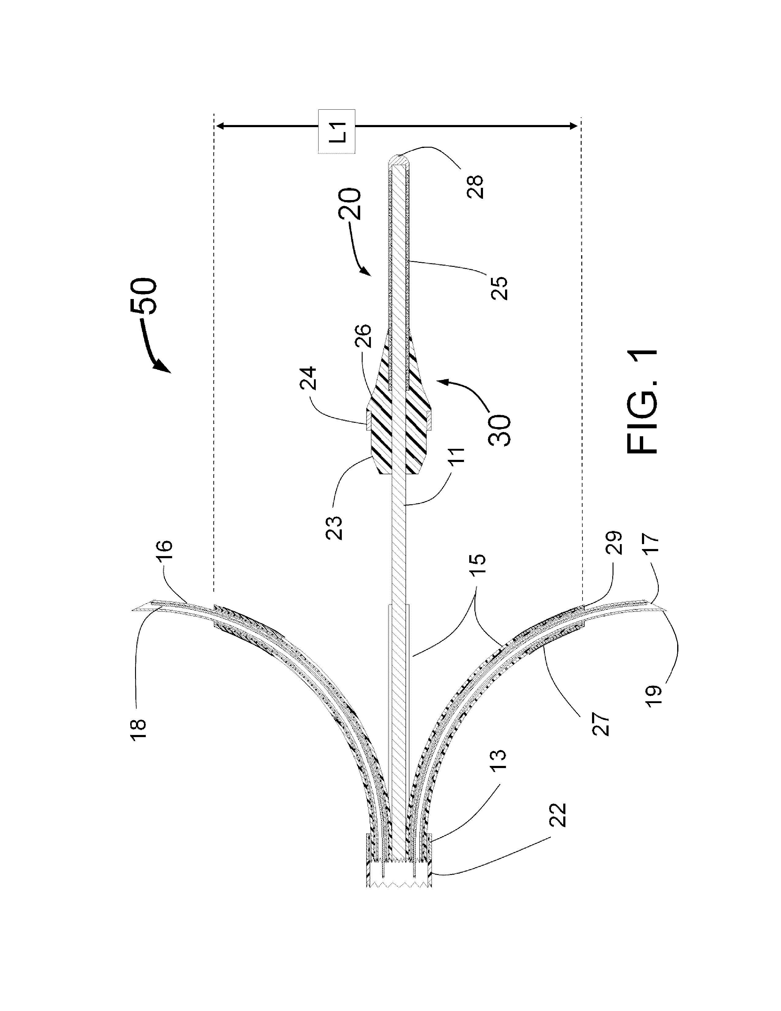
[0165]FIG. 1 is a longitudinal cross-section of the expanded distal portion of the invention by Fischell as described in U.S. patent application Ser. No. 13 / 643,070 filed on Oct. 23, 2012. This Intra-vascular Nerve Ablation System (INAS) 50 has a fixed guide wire 20 with tip 28 at its distal end. FIG. 1 shows the INAS 10 in its fully open position with the self-expanding guide tubes 15 with coaxial injector tubes 16 with sharpened distal injection needles 19 and needle distal opening 17 which is the injection egress deployed outward beyond the distal end 29 of the guide tubes 15. It should be understood that this embodiment of the INAS 50 has four injector tubes 16 protruding through four guide tubes 15. The guide tubes 15 are the needle guiding elements that help support the thin and flexible injector tubes 16 with distal injection needles 19 as they are advanced into the wall of a target vessel.

[0166]In this configuration, the sheath 22 has been pulled back to allow the guide tu...


PUM

PropertyMeasurementUnit
Fractionaaaaaaaaaa
Volumeaaaaaaaaaa
Radiusaaaaaaaaaa

Abstract

An intravascular catheter for peri-vascular and/or peri-urethral tissue ablation includes multiple needles advanced through supported guide tubes which expand with open ends around a central axis to engage the interior surface of the wall of the renal artery or other vessel of a human body allowing the injection an ablative fluid for ablating tissue, and/or nerve fibers in the outer layer or deep to the outer layer of the vessel, or in prostatic tissue. The system also includes means to limit and/or adjust the depth of penetration of the ablative fluid into and beyond the tissue of the vessel wall. The preferred embodiment of the catheter includes structures which provide radial and lateral support to the guide tubes so that the guide tubes open uniformly and maintain their position against the interior surface of the vessel wall as the sharpened injection needles are advanced to penetrate into the vessel wall.

Description

PRIORITY APPLICATIONS[0001]This application claims the benefit under 35 U.S.C. §119(e) as a nonprovisional of U.S. Provisional Patent Application No. 61 / 719,906, filed Oct. 29, 2012.FIELD OF THE INVENTION[0002]This invention is in the field of devices to ablate tissue and nerve fibers for the treatment of hypertension, congestive heart failure, BPH and prostate cancer and other disorders.BACKGROUND OF THE INVENTION[0003]Since the 1930s it has been known that injury or ablation of the sympathetic nerves in or near the outer layers of the renal arteries can dramatically reduce high blood pressure. As far back as 1952, alcohol has been used for tissue ablation in animal experiments. Specifically Robert M. Berne in “Hemodynamics and Sodium Excretion of Denervated Kidney in Anesthetized and Unanesthetized Dog” Am J Physiol, October 1952 171:(1) 148-158, describes painting alcohol on the outside of a dog's renal artery to produce denervation.[0004]Because of the similarities of anatomy, f...

Claims


Application Information

Patent Timeline
IPC IPC(8): A61M5/178A61M5/00
CPCA61M31/00A61B18/1492A61B18/1477A61B2018/00434A61B19/5225A61M5/00A61B2018/046A61M25/0084A61B2019/5466A61K31/045A61B18/00A61B2019/5238A61B2018/00285A61B2018/00577A61M2025/0087A61B2090/376A61B90/37A61B2090/3966
Inventor FISCHELL, DAVID R.FISCHELL, TIM A.RAGLAND, ROBERT RYANKENT, DARRIN JAMESDENISON, ANDY EDWARDJOHNSON, ERIC THOMASBURKE, JEFF ALANHAYDEN, CHRISTOPHER SCOTTFISCHELL, ROBERT E.
Owner ABLATIVE SOLUTIONS INC
Why Eureka
Try Eureka