Inline intravenous fluid sterilizer

a fluid sterilizer and intravenous technology, applied in the direction of disinfection, material analysis using wave/particle radiation, treatment water, etc., can solve the problems of affecting the quality and cost of healthcare globally, the overall cost to this country can exceed 2 billion dollars annually, and the opportunity for a sterility breach, etc., to achieve sufficient flow rate, prevent the formation of bubbles during use, and large surface area

Active Publication Date: 2014-06-10
B B R MEDICAL INNOVATIONS
View PDF8 Cites 24 Cited by
  • Summary
  • Abstract
  • Description
  • Claims
  • Application Information

AI Technical Summary

Benefits of technology

[0013]This invention overcomes the disadvantages of the prior art by providing an inline intravenous (IV) fluid sterilization system that can be located within the fluid system directly upstream of the patient's access point and downstream of any breach points so as to ensure that fluid entering the patient is sterile. This system avoids the use of filters and other elements that require periodic service by providing a cassette with a pair of concentric inner and outer walls defining a fluid space therebetween that enables capillary flow therethrough. The chamber space between the walls is accessed by a fluid inlet port and a fluid outlet port between which the fluid flows. The inlet port is connected to a conduit / tubing from the fluid source and the outlet port is interconnected with a conduit / tubing that is free of breach points and interconnects to the patient access point. The inner wall allows for transmission of UV light into the fluid space so as to deliver a sterilizing energy to the fluid that is sufficient to kill most or all of any microbiological life therein. The walls define a space therebetween (see wall spacing SW in FIG. 11A) that is relatively small / thin radially (a few millimeters at most), thereby allowing for a sufficient flow rate, but providing a large surface area and small fluid depth for exposure to the UV light. Illustratively, the UV light is provided by one or more elongated lamp(s) that is / are nested within a cavity of the inner wall. The elongated lamp(s) is / are mounted in a base unit that includes a shielding outer canister which includes a UV-opaque material that prevents transmission of UV light to the outside environment. The base unit can further include a clamp for mounting to an IV stand or pole, or other supporting structure. In an embodiment, flow through the fluid chamber occurs from a bottom-located inlet to a top located outlet with respect to the direction of gravity this assists in de-airing the unit and preventing formation of bubbles during use.

Problems solved by technology

The prevalence of nosocomial (hospital-acquired) infection adversely affects the quality and cost of healthcare globally.
With an average cost of treatment of such infections at $15,000 per incident, the overall cost to this country can exceed 2 billion dollars annually.
Any manipulation or perturbation to the integrity of the closed intravenous system can create an opportunity for a breach in the sterility.
In immuno-compromised patients, and in fluids that may in fact support bacterial growth, the risk for significant infection is ever greater.
This creates the opportunity for contamination of the system at, for example, the fluid interface (e.g. a luer fitting).
Presently, there are no available reliable commercial mechanisms for rendering parenteral fluid, or any fluid meant for infusion into patients, re-sterilized in real-time, if the sterile condition is breached, short of replacing the fluid and intravenous tubing assembly.
A pore size of 0.22 microns is necessary for sterile filtration, but such a smaller pore size rating would typically create a greater resistance to flow, and is not tenable for the general range of IV fluid flow rates required in surgery and in treating critically ill patients.
Furthermore, periodic removal of such an inline filter as it becomes filled with particulates, and its efficiency diminishes, can leave open the possibility for further breaches in the sterile barrier.
These are not necessarily viable options as there may be detrimental effects upon structural components of blood and pharmaceutical products.

Method used


Image

  • Inline intravenous fluid sterilizer
  • Inline intravenous fluid sterilizer
  • Inline intravenous fluid sterilizer

Examples


Embodiment Construction

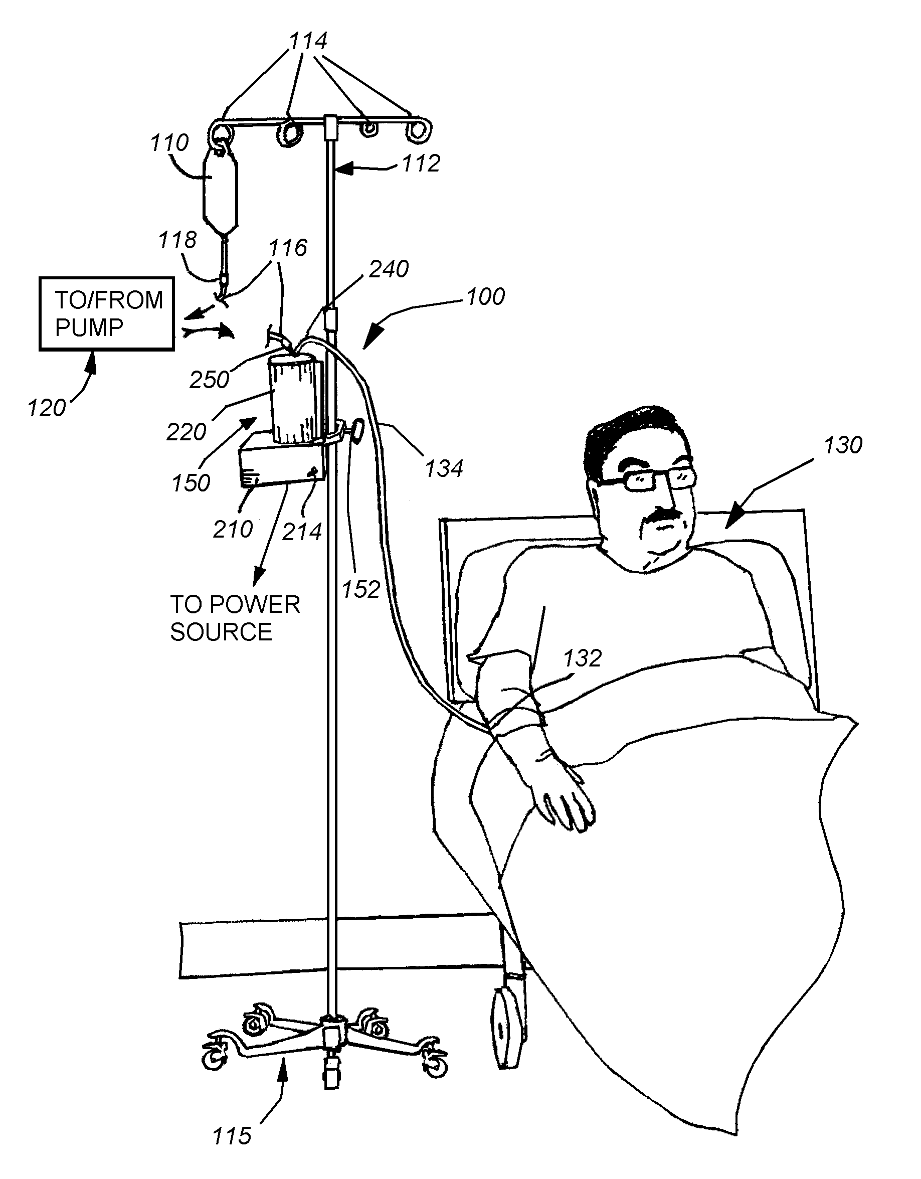
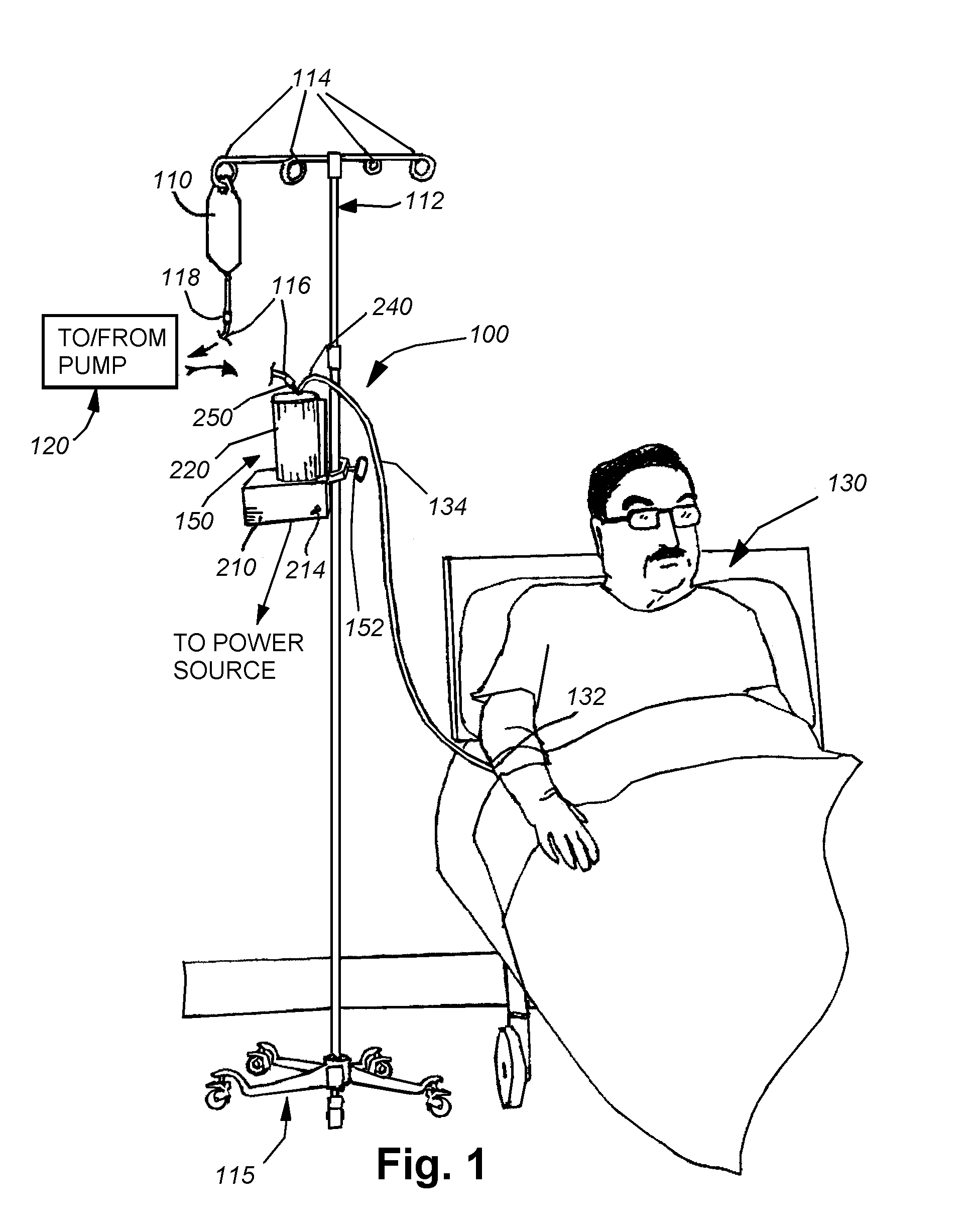
[0034]As shown in FIG. 1, an exemplary arrangement of an intravenous (IV) fluid delivery system 100. The system 100 typically includes a source, such as a conventional IV fluid bag 110, containing an appropriate therapeutic agent in fluid solution. In further embodiments, a combination of fluids, with appropriate mixers and / or stopcock systems can be provided. The bag is mounted on an IV stand or pole 112 including a plurality of associated hanging hooks 114 that are adapted to suspend bags for effective gravity feed of the fluid through a tubing system. The stand can be fixed or portable, as provided by the caster base 115. The bag 110 is adapted to be replaced with a new full bag as needed by manipulating a conventional Luer Lock interconnection 118 and / or a spike interconnection that engages the bag 110. A proximal tubing section 116 is interconnected to the bag via the fitting 118. While not shown, a variety of other fittings can be employed along the tubing 116, including stopc...


PUM

PropertyMeasurementUnit
pore sizeaaaaaaaaaa
lengthaaaaaaaaaa
wavelengthaaaaaaaaaa

Abstract

An inline intravenous (IV) fluid sterilization system can be located within directly upstream of the patient's access point, downstream of any breach points, so as to ensure fluid sterility. The chamber space between the walls is accessed by a fluid inlet port and a fluid outlet port between which the fluid flows. The inlet port is connected to a conduit / tubing from the fluid source and the outlet port is interconnected with a conduit / tubing that is free of breach points and interconnects to the patient access point. The inner wall allows for transmission of UV light into the fluid space. The walls define a space therebetween that is relatively small radially, allowing for a sufficient flow rate, but providing a large surface area and small fluid depth for exposure to the UV light. The UV light is provided by an elongated lamp within a cavity of the inner wall.

Description

RELATED APPLICATIONS[0001]This application claims the benefit of U.S. Provisional Application Ser. No. 61 / 164,254, filed Mar. 27, 2009, entitled INLINE INTRAVENOUS FLUID STERILIZER, the entire disclosure of which is herein incorporated by reference.FIELD OF THE INVENTION[0002]This invention relates to fluid sterilization systems for use in conjunction with an intravenous (IV) fluid-delivery system and more particularly to sterilization systems employing ultraviolet (UV) radiation.BACKGROUND OF THE INVENTION[0003]The prevalence of nosocomial (hospital-acquired) infection adversely affects the quality and cost of healthcare globally. Primary bloodstream infections, which are typically precipitated by intravenous infusions, account for 8% of all nosocomial infections. A heightened awareness of transmission of potentially pathogenic bacterial organisms has lead to implementation of various preventative measures. In the United States alone, 50,000 to 120,000 patients per year develop inf...

Claims


Application Information

Patent Timeline
Patent Type & Authority Patents(United States)
IPC IPC(8): C02F1/32C02F1/48
CPCC02F2301/026A61L2/0047C02F2201/3223C02F2201/328C02F1/325C02F1/48C02F1/32C02F2303/04C02F2201/007A61L2/00A61L9/00C02F2103/026C02F2201/004A61L2/10
Inventor BURCHMAN, COREY A.REINITZ, STEVEN D.BOUCHER, KATHRYN E.COTTLE, RENEE N.
Owner B B R MEDICAL INNOVATIONS
Why Eureka
Try Eureka