Supercharge Your Innovation With Domain-Expert AI Agents!

Two-stage pulse signal controller

a pulse signal controller and two-stage technology, applied in the direction of pulse technique, electric controller, instruments, etc., can solve the problem that the device cannot reach the target value, and achieve the effect of improving the precision of pwm control

Active Publication Date: 2014-06-17
YAN MI +1
View PDF42 Cites 2 Cited by
  • Summary
  • Abstract
  • Description
  • Claims
  • Application Information

AI Technical Summary

Benefits of technology

This approach enhances control performance by compensating for variations in plant parameters and full-scale levels within the control loop, reducing the need for high precision driving sources and robust plants, thereby improving system stability and precision without increasing system complexity.

Problems solved by technology

A fault is reported when the PWM signal is not capable to drive the device, i.e., at full capacity of the PWM signal, the device is not able to reach the target value.

Method used


Image

  • Two-stage pulse signal controller
  • Two-stage pulse signal controller
  • Two-stage pulse signal controller

Examples


Embodiment Construction

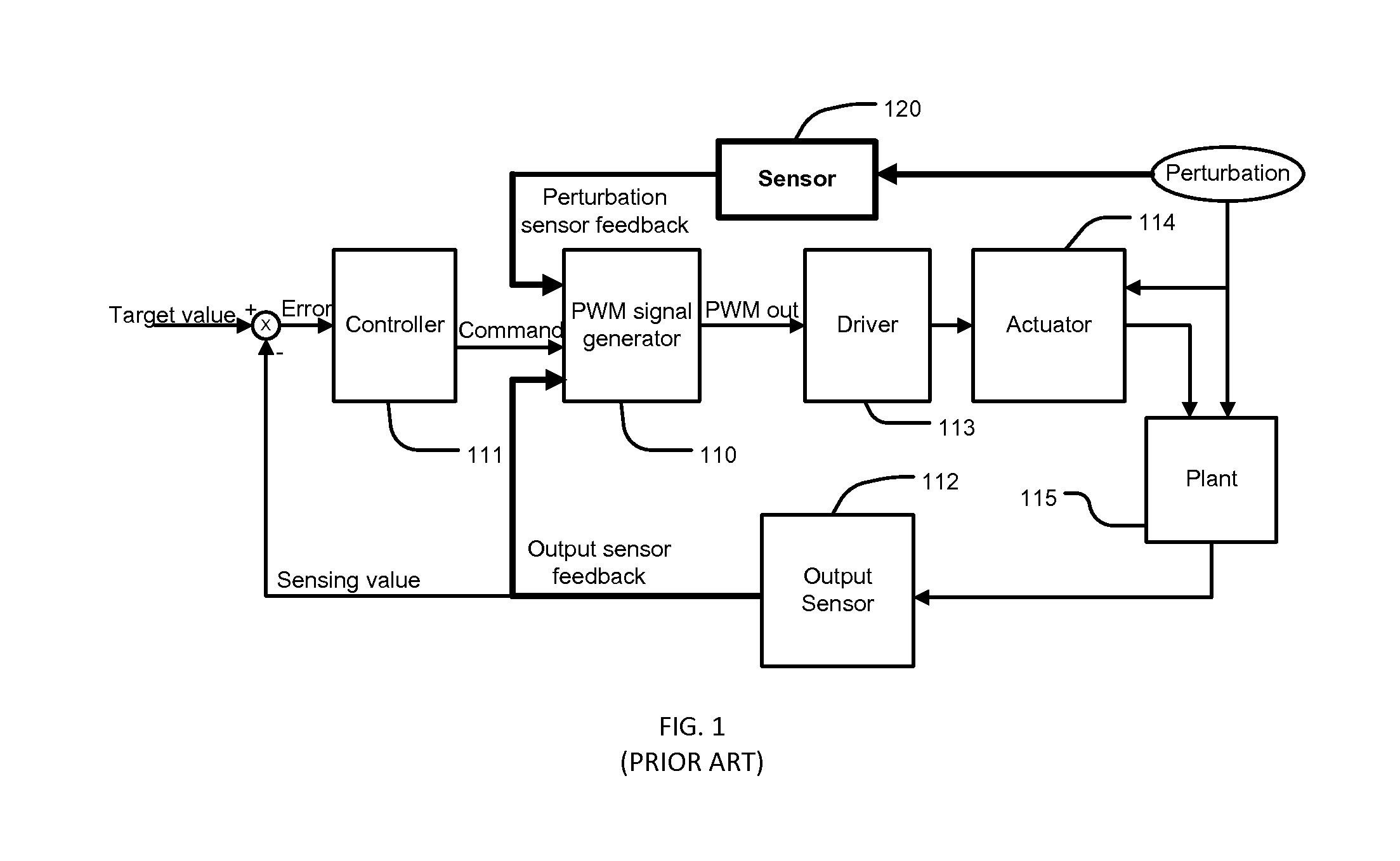
[0033]In a control system shown in FIG. 1, a control signal is generated by a pulse signal generator 110 for a driver 113 to switch on and off an actuator 114 in the control loop. The actuator 114 provides controls to a plant 115, and an output sensor 112 is used to monitor the output of the plant. The sensing value obtained from the output sensor 112 is compared to a target value, and the difference or error between the target value and the sensing value is used by a controller 111 in generating command signals to the pulse signal generator 110. Such a control system is broadly used in controlling power to inertial devices and flow rate controls. In this control system, normally the pulse control signal provided to the actuator 114 can be generated accurately. However, in the actuator 114 and the plant 115, perturbation may exist causing changes in parameter values and deterioration in system control performance. To increase the robustness and performance of the system, a perturbat...


PUM


Abstract

An apparatus and method for controlling a device using pulse signals. In the apparatus and method, a two-stage control is used to generate pulse signals, which can be a PWM signal, a pulse signal including a PWM signal with a sleeping time, or a PDM signal. The two-stage control includes a second stage control, which generates pulse signals according to parameter values generated periodically by a first stage according to a target value and feedback sensing values. The two-stage control can be used in decreasing perturbation in a closed-loop control and accurate open-loop control.

Description

CROSS-REFERENCE TO RELATED APPLICATIONS[0001]Not ApplicableSTATEMENT REGARDING FEDERALLY SPONSORED RESEARCH OR DEVELOPMENT[0002]Not ApplicableREFERENCE TO SEQUENCE LISTING, A TABLE, OR A COMPUTER PROGRAM LISTING COMPACT DISC APPENDIX[0003]Not ApplicableFIELD OF THE INVENTION[0004]This present application claims priority from U.S. provisional application No. 61 / 574,469 having the same title as the present invention and filed on Aug. 3, 2011.[0005]This invention relates to apparatus and methods for driving an actuator using pulse control signals.BACKGROUND OF THE INVENTION[0006]Pulse signals, such as pulse-width modulated (PWM) signals and pulse-duration modulated (PDM) signals, are used in controlling power applied to inertial devices and directly controlling average values, e.g. average flow-rate. A PWM or PDM signal is determined by two parameters: a PWM period and an on-time or duty cycle, which is the ratio of the on-time to the PWM period. Normally, in an application, the PWM pe...

Claims


Application Information

Patent Timeline
Patent Type & Authority Patents(United States)
IPC IPC(8): H03K3/017G05B11/28H03K7/08
CPCH05B1/0244
Inventor YAN, MIQI, BAOHUA
Owner YAN MI
Features
  • R&D
  • Intellectual Property
  • Life Sciences
  • Materials
  • Tech Scout
  • Unparalleled Data Quality
  • Higher Quality Content
  • 60% Fewer Hallucinations
Learn More