Submerged electricity generation plane with marine current-driven rotors

a technology of current-driven rotors and electricity generation planes, which is applied in the direction of electric generator control, special-purpose vessels, vessel construction, etc., can solve the problems of maintenance of underwater systems, high underwater construction costs, and low power output, so as to reduce the effect of buoyancy, increase the drag load, and reduce the speed

Inactive Publication Date: 2014-07-01
AQUANTIS
View PDF21 Cites 16 Cited by
  • Summary
  • Abstract
  • Description
  • Claims
  • Application Information

AI Technical Summary

Benefits of technology

[0017]In accordance with the present invention, an apparatus for underwater power-generation is provided in which a submersible device, or platform, includes sets of two or more counter-rotating rotor assemblies, each rotor assembly having rotor blades, preferably of fixed pitch. The current-driven rotor assemblies drive hydraulic pumps which, in turn, drive fixed and variable displacement hydraulic motors to drive, preferably at constant speed, electric generators that are all housed in a fluid-tight power pod. The power pods are connected together by a transverse structure, which can be a wing depressor built in the shape of a hydrofoil, a truss, or a faired tube. The submersible device is connected to one or more anchors on the seabed by forward tethers. The device is also connected to an additional anchor on the seabed by a vertical downward tether to limit the submersible device to a desired depth, to prevent unplanned surfacing, and to counteract buoyancy. The vertical current shear has lower velocity as depth increases. A wing depressor generates negative lift to offset buoyancy and ensures that the submersible device seeks / dives down to the desired operational current speed along the vertical shear, which corresponds to a specific depth. The same effect can be accomplished with a truss or faired tube, in concert with dominating rotor drag loads. As the flow velocity varies above operational speed, thereby increasing drag loads, the device dives deeper along the vertical shear until it reaches equilibrium (balance of forces) at the corresponding flow speed.

Problems solved by technology

This type of design has several disadvantages: higher underwater construction costs; the engineering challenges related to installing towers in deep water; reduced current velocity close to the ocean floor resulting in lower power output; and maintenance of underwater systems.
Many countries throughout the world rely heavily on importing fuel for generating electricity, and they lack other viable renewable energy sources.
Some of the patents describe devices using active stability, depth and rotor control, which increases cost and reduces reliability.
In a moored system with harsh environmental and structural loading from ocean tidal currents, gyres (steady ocean currents), and eddies, failures from these control methods could result in the inability to access the device, or, in the worst cases, complete loss of the structure, or hazard to navigation for vessels using the area.
In addition to the inherent risks, these controls lack simplicity; they provide many variables and opportunities for failure, along with the additional costs associated with these types of control methods.
Lower reliability, lower operating availability for power production, and higher maintenance requirements mean that the designs shown in the prior art are not cost-effective.
For example, accessing the mechanical components of submerged systems can require specialized crews, divers, autonomous underwater vehicles (AUV's), Remotely Operated Vehicles (ROV's), vessel costs for mobilization and demobilization, and related fuel costs.

Method used


Image

  • Submerged electricity generation plane with marine current-driven rotors
  • Submerged electricity generation plane with marine current-driven rotors
  • Submerged electricity generation plane with marine current-driven rotors

Examples


Embodiment Construction

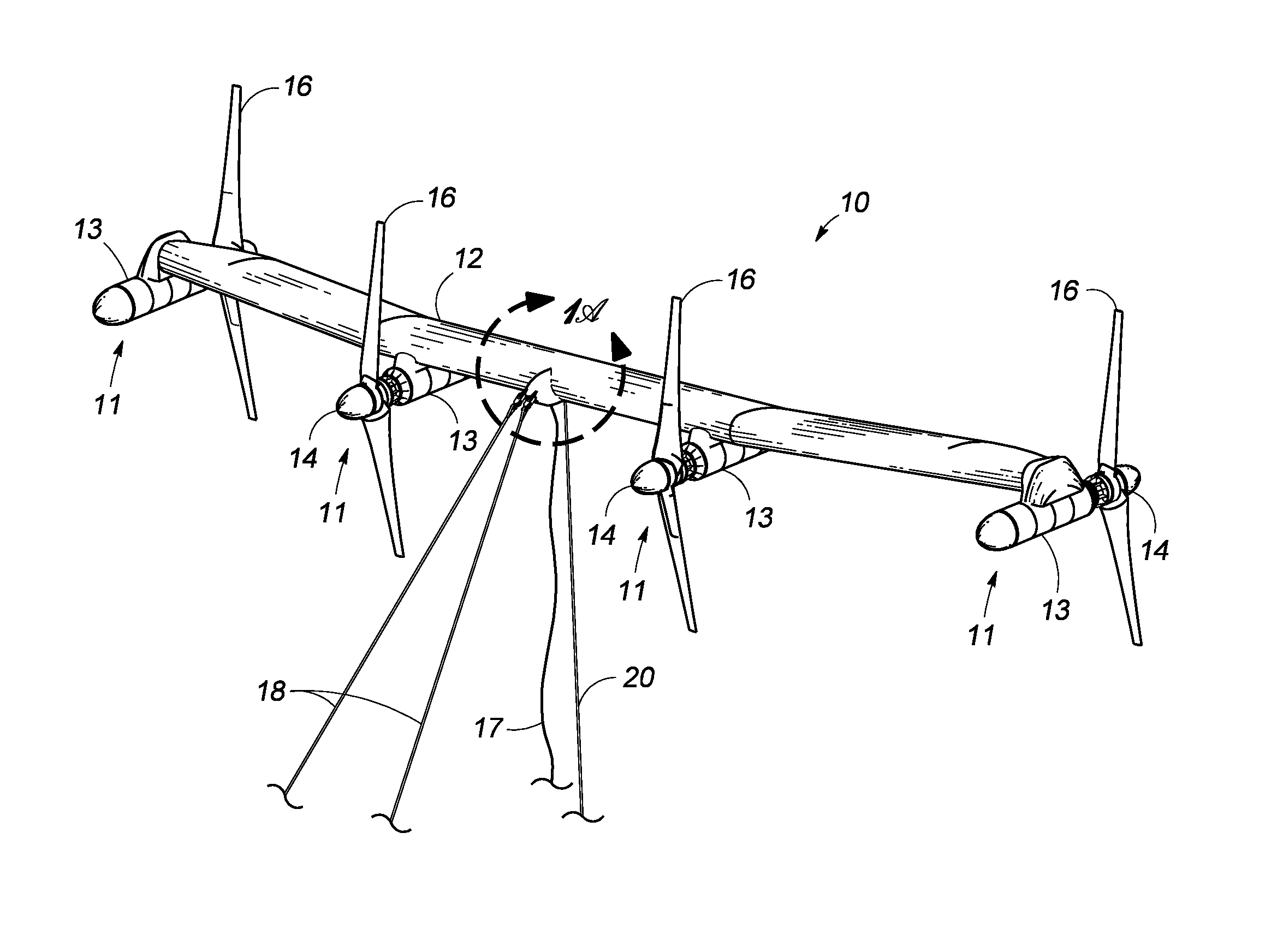
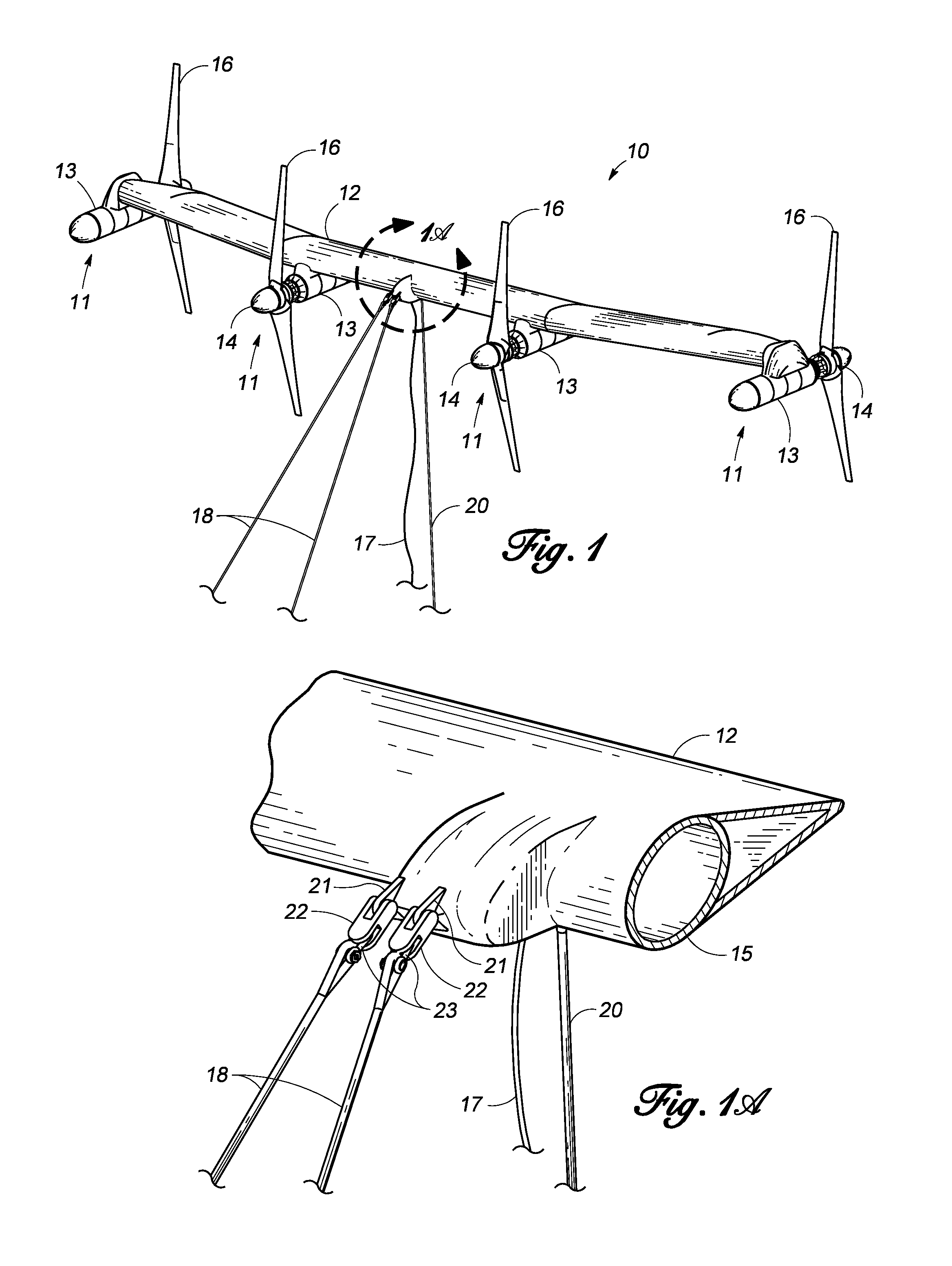
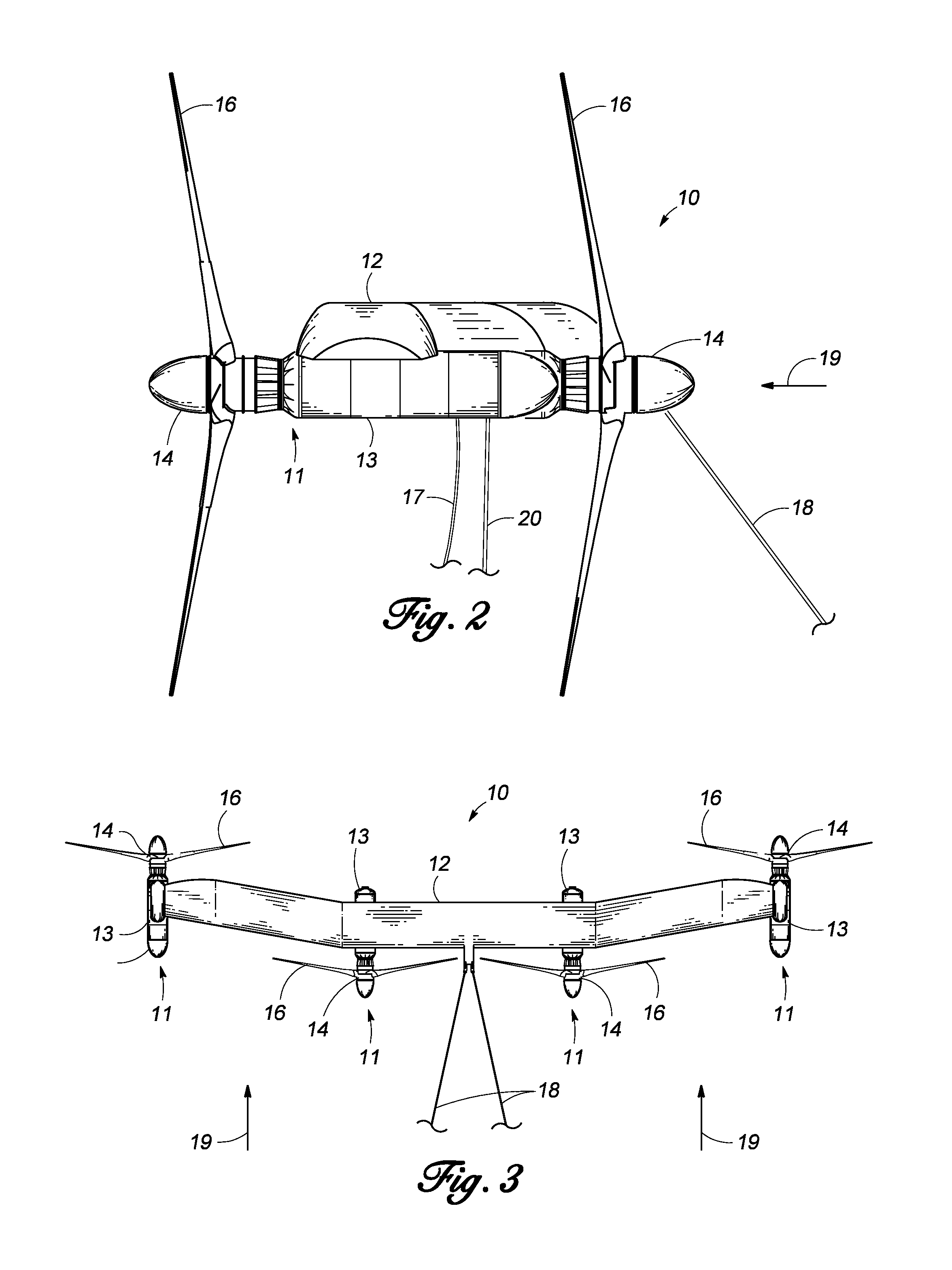
[0087]The present invention described herein is intended for marine current underwater power generation with passive depth control.

[0088]FIGS. 1, 2 and 3 illustrate a submersible multi-megawatt power plant that will be referred to as the platform 10. These figures show the platform 10 in a perspective view, a side view, and plan view. This variation of the platform 10 has four power pods 11, each rigidly connected to the transverse structural wing 12. The wing 12 can be formed in a number of ways, depending on design choice, including a faired tube 15, as shown in FIG. 1A, or a truss 31, as shown in FIG. 7, infra. The power pod 11 is comprised of a dry, buoyant pressure vessel 13 (containing a bearing and seal assembly and drivetrain) and a wet rotor assembly 14 with two fixed pitch rotor blades 16. The power pods 11 and structural wing 12 contain all of the equipment necessary for generating and supplying electricity via a riser cable 17 to the electric power collection system for ...


PUM


Abstract

An underwater apparatus for generating electric power from ocean currents and deep water tides. A submersible platform including two or more power pods, each having a rotor with fixed-pitch blades, with drivetrains housed in pressure vessels that are connected by a transverse structure providing buoyancy, which can be a wing depressor, hydrofoil, truss, or faired tube. The platform is connected to anchors on the seafloor by forward mooring lines and a vertical mooring line that restricts the depth of the device in the water column. The platform operates using passive, rather than active, depth control. The wing depressor, along with rotor drag loads, ensures the platform seeks the desired operational current velocity. The rotors are directly coupled to a hydraulic pump that drives at least one constant-speed hydraulic-motor generator set and enables hydraulic braking. A fluidic bearing decouples non-torque rotor loads to the main shaft driving the hydraulic pumps.

Description

STATEMENT REGARDING FEDERALLY SPONSORED RESEARCH OR DEVELOPMENT[0001]This invention was made with Government support under the terms of Grant No. DE-EE0002648 awarded by the Department of Energy. The Government has certain rights in this invention.CROSS REFERENCE TO RELATED APPLICATION[0002]This application claims the benefit of U.S. Provisional Application No. 61 / 628,518, filed Oct. 31, 2011.BACKGROUND OF THE INVENTION[0003]1. Field of the Invention[0004]This invention relates to hydroelectric power-generating devices that use underwater currents to drive electricity-generating rotor assemblies.[0005]2. Description of the Prior Art[0006]The use of underwater power generators for generating electricity from water current flow, such as rivers and oceans, is known in the art. There are two types of prior art ocean devices: stationary turbines and tethered turbines. Stationary turbines are comprised of stationary towers based on the ocean floor. Electricity-generating turbines are moun...

Claims


Application Information

Patent Timeline
Patent Type & Authority Patents(United States)
IPC IPC(8): F03B13/10
CPCB63B22/02B63B21/26F03B13/105Y02E10/28B63B21/50F05B2240/97Y02E10/38F03B17/061F05B2260/902F05B2270/18F03B3/04F05B2260/406B63G8/22B63B35/44B63B2035/4466Y02E10/20Y02E10/30
Inventor DEHLSEN, JAMES G. P.DEHLSEN, JAMES B.FLEMING, ALEXANDER
Owner AQUANTIS
Why Eureka
Try Eureka