Sampling of non-planar display surfaces

a non-planar display surface and sampling technology, applied in the field of computer graphics, can solve the problems of introducing photometric distortion, introducing geometric distortion, and very expensive creation of optics, and achieve the effects of controlling the computational burden of filters, improving sampling, and optimizing image quality

Active Publication Date: 2014-07-01
AECHELON TECH
View PDF7 Cites 24 Cited by
  • Summary
  • Abstract
  • Description
  • Claims
  • Application Information

AI Technical Summary

Benefits of technology

[0012]The present invention enables a system and method for improving sampling in the process of trans-raster distortion correction. The distortion parameterization is analyzed to determine the maximum inflation and deflation (magnification and minification) over the image. The maximum inflation is then used to determine the optimal resolution (e.g., dimensions in pixels) of the linear-projected image such that it is not undersampled by the output image. The maximum deflation, coupled with the optimal resolution determined in the inflation step, is then used to configure the filter used in the resampling process such that aliasing due to undersampling is minimized, while simultaneously controlling the computational burden of the filter.
[0013]The present invention optimizes image quality in trans-raster Nonlinear Image Mapping (NLIM) systems. In one embodiment, the NLIM system is applied to projection on non-planar surfaces, but those skilled in the art will recognize that the present invention applies equally well to other trans-raster NLIM applications. Image quality is optimized by analyzing the warp transformation to quantify the amount of distortion (inflation and deflation) applied to a linearly projected image to produce the warped image. The maximum inflation in each axis is used to calculate the dimensions of the linear-projected raster grid, and the maximum deflation, coupled with the ratio of input to output resolution, is used to configure the filter used in the trans-raster resampling process. In addition to improving the image quality, the present invention controls computational complexity in the 3D rendering and resampling steps by tailoring their parameters to the specific NLIM parameters, as opposed to a brute-force approach of rendering at a large multiple of the display resolution and implementing a resampling filter with many taps.

Problems solved by technology

Unlike a pinhole camera, which projects light without any defocusing or distortion, lenses are configured for a specific optical geometry, and any deviation from that geometry can introduce geometric distortion.
Lenses themselves may introduce photometric distortion, as is the case with a fisheye lens.
Creating such optics is very costly, as they are limited to a single geometry that can conflict with the purpose of the display e.g., locating the lens at the center of the dome.
Most modern projection technologies, e.g., LCD, DLP, and LCoS, also utilize digital raster array devices to modulate light, so no curve tracing is possible.
Undersampling, which causes input pixels to be magnified, will exaggerate aliasing that is inherent in the 3D rasterization process.
Oversampling, which causes input pixels to be minified, will introduce its own aliasing artifacts.

Method used


Image

  • Sampling of non-planar display surfaces
  • Sampling of non-planar display surfaces
  • Sampling of non-planar display surfaces

Examples


Embodiment Construction

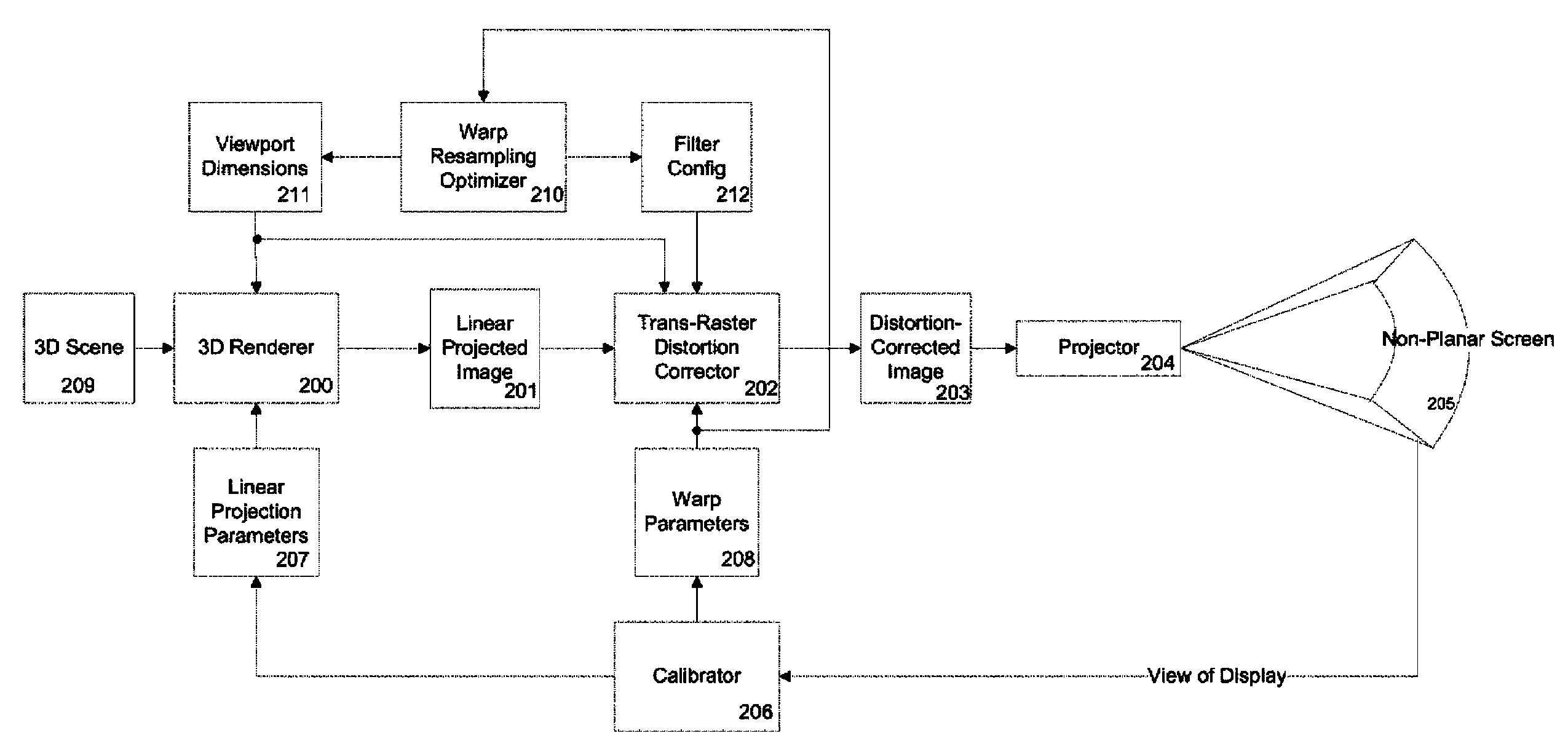
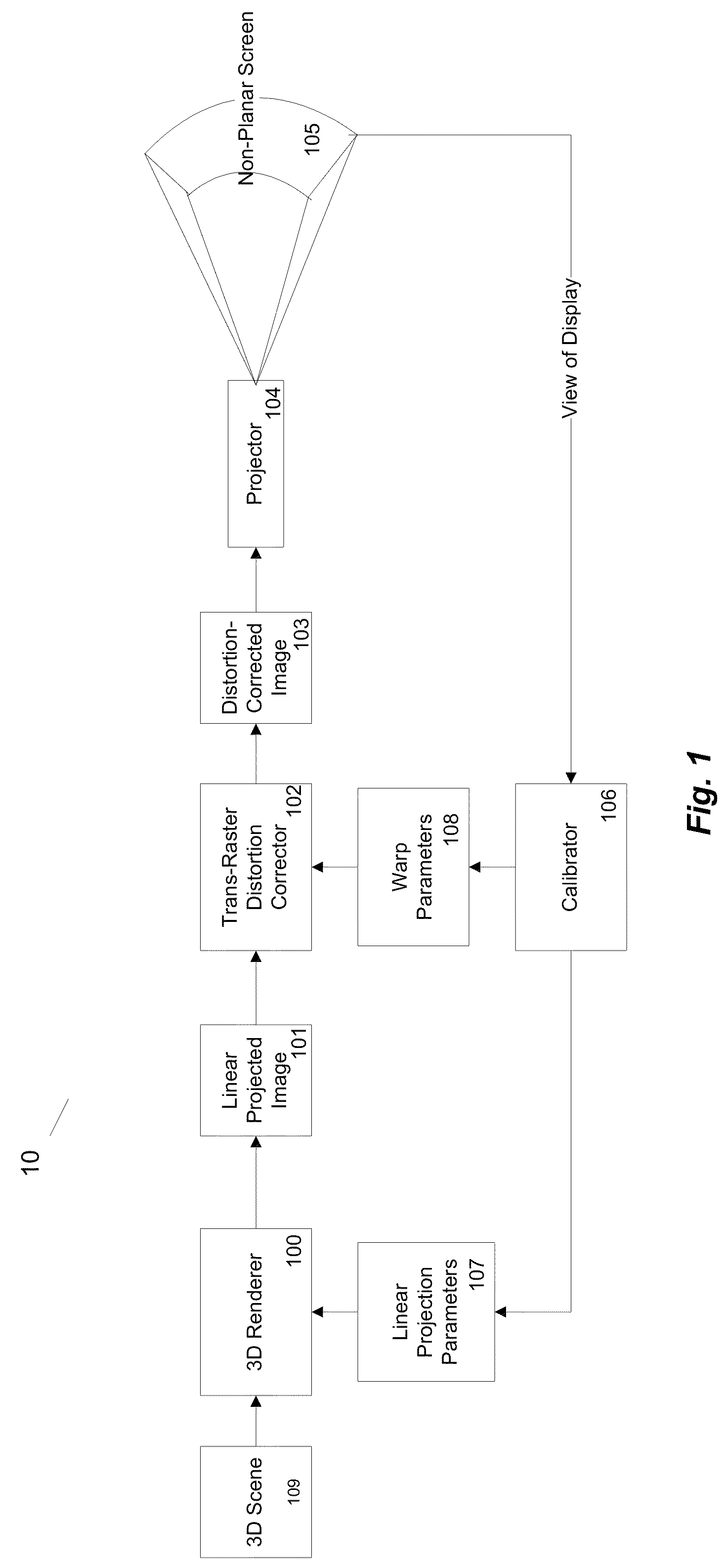
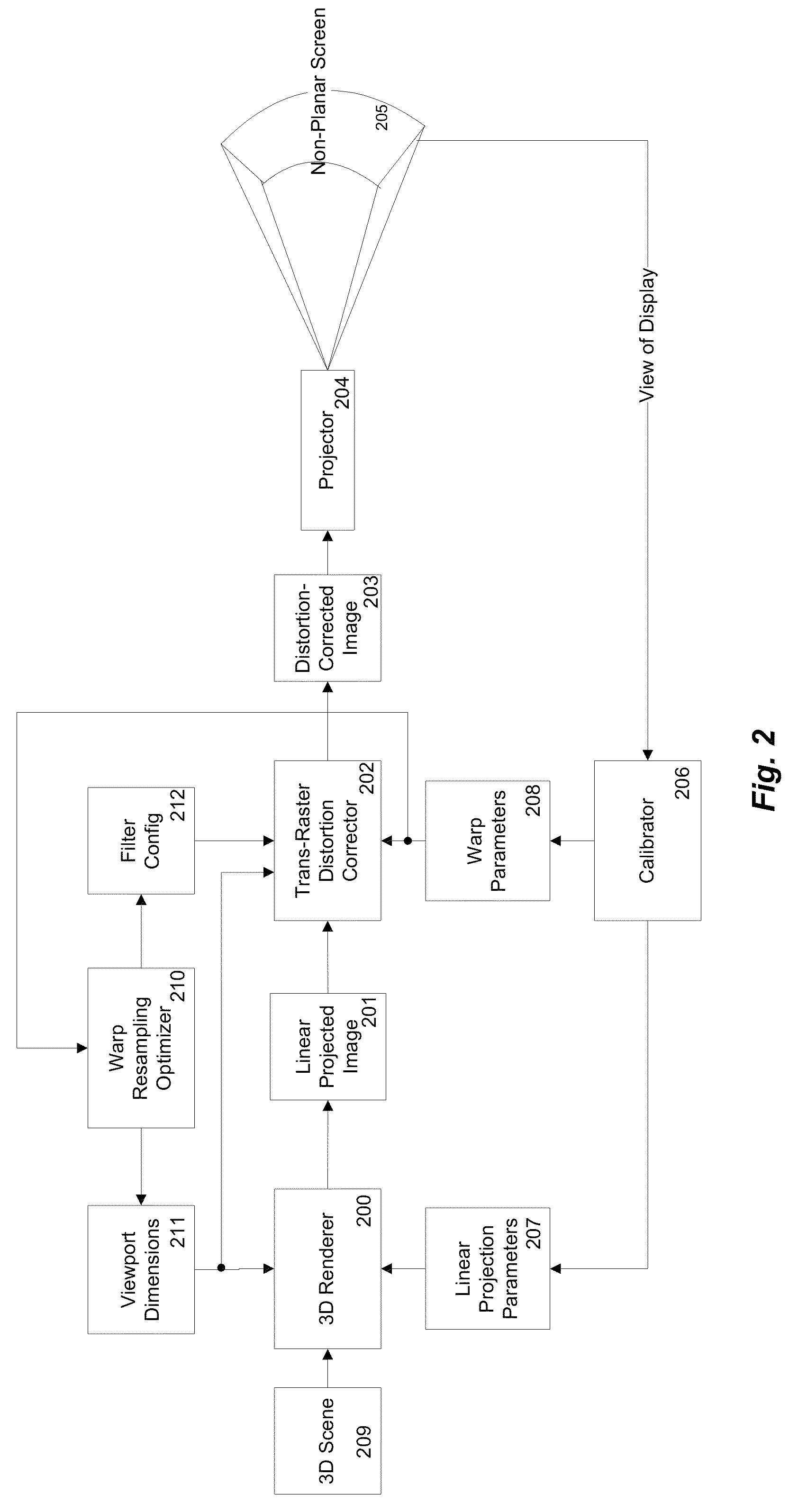
[0019]FIG. 1 illustrates a system 10 for generalized trans-raster NLIM in accordance with an embodiment of the present invention. A three-dimensional (3D) renderer 100 linearly projects and rasterizes a 3D scene 109 into a linear projected image 101. Linear projection parameters 107, in one embodiment including a 4×4 view matrix and a 4×4 projection matrix, govern the orientation and field of view of the virtual camera governing the linear projection. Linear projected image 101, which is a two-dimensional raster image, is then processed by trans-raster distortion corrector 102, which resamples image 101 according to warp parameters 108, to produce distortion-corrected image 103, which is also a 2D raster image, typically having dimensions equal to projector 104's native resolution. Warp parameters 108 establish a mapping from points in linear raster space to points in distorted raster space. Warp parameters 108 may be embodied as a distortion mesh, a look-up table, a set of control ...


PUM


Abstract

Sampling in the process of trans-raster distortion correction is described. The distortion parameterization is analyzed to determine the maximum inflation and deflation (magnification and minification) over the image. The maximum inflation is then used to determine the optimal resolution (dimensions in pixels) of the linear-projected image such that it is not undersampled by the output image. The maximum deflation, coupled with the optimal resolution determined in the inflation step, is then used to configure the filter used in the resampling process such that aliasing due to undersampling is minimized, while simultaneously controlling the computational burden of the filter.

Description

CROSS REFERENCE TO RELATED APPLICATIONS[0001]This application claims the benefit of U.S. Provisional Application 61 / 091,309, filed on Aug. 22, 2008, which is incorporated by reference in its entirety.BACKGROUND[0002]1. Field of the Invention[0003]The Present invention relates to the field of computer graphics, and in particular to Nonlinear Image Mapping (NLIM).[0004]2. Description of Related Art[0005]Since the earliest days of 3D computer graphics, generated images have been displayed on non-planar screens. Shapes such as spherical domes, toroidal sections, polyhedrons, and other types of surfaces have been used as screens. A variety of projector technologies have been used over the years to illuminate these screens, ranging from raster and calligraphic CRTs to light valves, LCDs, LCOS, DLP, and even scanning laser projectors. With the exception of laser projectors, all of these display devices direct their light through one or more lenses.[0006]Unlike a pinhole camera, which proje...

Claims


Application Information

Patent Timeline
Patent Type & Authority Patents(United States)
IPC IPC(8): G06T15/00G09G5/00
CPCG09G5/00H04N9/31G06T15/00G06T17/00H04N9/3185H04N9/3194
Inventor MORGAN, III, DAVID L.SANZ-PASTOR, IGNACIO
Owner AECHELON TECH
Why Eureka
Try Eureka