Method and system for compensating asymmetrical delays

a technology of asymmetric delay and delay, applied in the field of method and system for compensating asymmetric delay, can solve the problems of stochastic delay, high transmission channel demand, and both systematic asymmetric delay, and achieve the effects of reducing quality, increasing the immunity of data transmission system, and increasing economic benefits

Inactive Publication Date: 2012-12-11
ROBERT BOSCH GMBH
View PDF13 Cites 2 Cited by
  • Summary
  • Abstract
  • Description
  • Claims
  • Application Information

AI Technical Summary

Benefits of technology

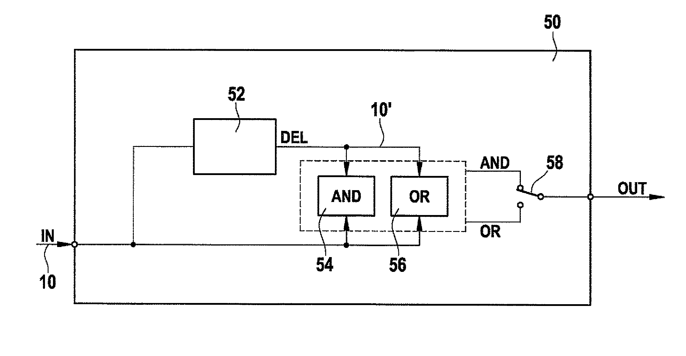
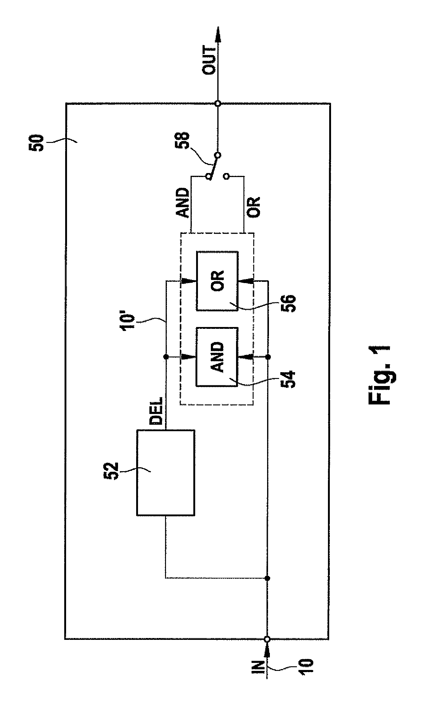
[0020]An advantage of the present invention is that it allows a compensation of the asymmetrical delay of transmitted signals, or an increase in the immunity of the data-transmission system to asymmetrical delays, without the need for modifications on the logical level of the receiving users or their communications controller. According to example embodiments of the present invention, the asymmetrical delay is thus reduced or possibly even compensated on the physical level in the transmission channel, so that merely a slight or possibly no asymmetrical delay may still be detectable in the receiving users. This has the advantage that conventional modules, possibly even of lower quality and thus considerably more economical modules, may be utilized for communications-controller and / or transceiver components in the receiving users without the occurrence of decoding errors.
[0021]Of course, it is also possible to use the present invention for the users proposed in German Patent Application No. DE 10 2005 037 263 and German Patent Application No. DE 10 2005 060 903 with improved sampling of the received signal.
[0022]An embodiment of the present invention is described by way of example based on a FlexRay data transmission system. However, this is not to be understood as a restriction with regard to the present invention. Instead, the present invention may be used for many different types of data-transmission systems and is readily transferable to comparable systems. In particular, it is possible to use the present invention in data-transmission systems that transmit data according to the TTP / C (time triggered protocol class C), the CAN (controller area network) or the TTCAN (time triggered CAN) protocol.
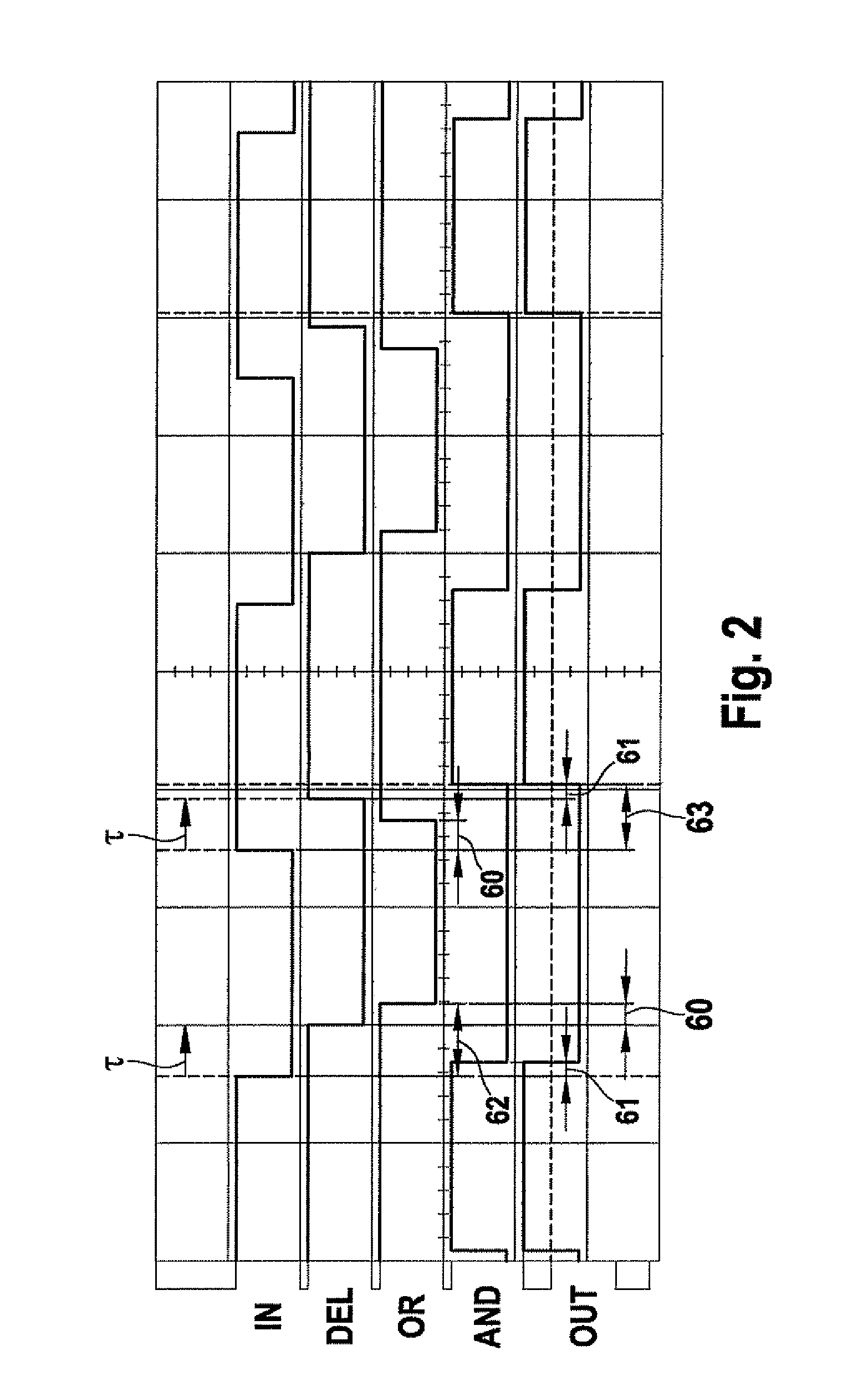
[0023]In FlexRay data-transmission systems, a nominal bit length of 100 ns results at a data-transmission rate of 10 Mbit / sec. Currently available FlexRay transceiver modules generally require a minimum bit time of approximately 80 ns; shorter bit times are no longer able to be detected or processed by the transceiver modules without additional restrictions such as additional asymmetry. However, asymmetrical delays of the transmitted signals lead to partly considerably shortened bit times in the receiving user. For example, given an asymmetrical delay of 60 ns, the nominal bit length of 100 ns is shorted to a bit length of only 40 ns. The current FlexRay transceiver modules could not at all process such short bit times. However, the present invention may make it possible to reduce the asymmetrical delay considerably, for instance to 5 ns, so that the bit length available at the receiving user still amounts to 95 ns and thus lies considerably above the minimum bit length of approximately 80 ns required by the FlexRay transceiver module.
[0024]According to an advantageous further development of the present invention, the asymmetrical delay is measured with the aid of an interval in a change of the signal from rising to falling edge or from falling to rising edge absolutely required in a transmission protocol used in the data-transmission system. In an advantageous manner, the interval between a rising edge of a frame start sequence (FSS) and a falling edge of a byte start sequence (BSS) of a data frame is measured. The measurement is preferably carried out at least once for each active data transmission path. In this context, an increase in the number of the measured values reduces the influence of stochastic corruptions. In particular, the measurements can also be continued during the data transmission and the compensation of the asymmetrical delay be adaptively adjusted even prior to the decoding of the data bits, in the course of the transmission. It is also possible to detect errors if contradictory measured values for the asymmetrical delay should result from multiple measurements.
[0025]It is possible to provide programmable delay units at one or several random points in the network structure of the data-transmission system, which selectively reduce or even compensate the asymmetrical delay of the transmitted signals. The compensation of the asymmetrical delay with the aid of the programmable delay unit may be implemented on the basis of values for the asymmetrical delay of the signal determined prior to the use of the data-transmission system, i.e., prior to the actual data transmission. The determination of the asymmetrical delay values in advance of the data transmission may take place at the factory, for example, or on the basis of the ready-for-use data-transmission system installed in a motor vehicle, for instance, by estimation, modeling or measuring.

Problems solved by technology

This is difficult especially when the sampling instant refers to a flank of the signal and also analyzes a plurality of binary data values (bits) of the transmitter relative thereto, over many periods of the sampling clock.
It has become clear that the rigid specification of the sampling instant without considering the asymmetrical delays on the different transmission paths leads to problems.
Asymmetrical delays may have both systematic and stochastic causes.
Stochastic delays have effects both on the rising and on the falling edges, and are caused by noise occurrences or EMC jitter.
Because of the fixed selection of the sampling instant per bit (for example, at n / 2, in the middle of a bit, given n sampling values per bit), both the influence of the asymmetrical distortion as well as the frequency deviation and the additional time discretization by the sampling is a problem and place high demands on the transmission channel.
Increasing the edge steepness so as to reduce the asymmetrical delays would indeed be advantageous for the timing, but on the other hand would require technically more sophisticated and thus more expensive components and, in addition, could have an adverse effect on the EMC response of the data transmission system.
Therefore, it is sometimes more advantageous not to select the edge steepness to be so great; however, depending on the pulse distortion, one runs the risk of evaluating the wrong datum either at the one or the other bit boundary.
When realizing FlexRay data transmission systems, in particular in the case of complex systems that include a plurality of star couplers and passive networks, it has also been shown that the asymmetrical delay times that occur there are so great that they exceed a time budget specified by the FlexRay protocol.
However, as may be the case in complex network topologies or network structures, if the asymmetrical delay exceeds the provided time budget, then this leads an incorrect value being determined in a sampling at the fifth sampling cycle (counter reading of the cycle counter at 5), since the particular bit that should have been sampled was already available at an earlier instant due to the asymmetrical delay and is no longer present due to the early edge change.
If the time budget is exceeded in a manner advanced or retarded in time, decoding errors result, that is to say, false data are received.
However, if the error detection algorithm responds too frequently, there is the disadvantage of the attendant reduced availability of the data transmission system.
Furthermore, it is possible that the asymmetrical delay of the transmitted signal is determined online, so to speak, during the operation of the data-transmission system.
Currently available FlexRay transceiver modules generally require a minimum bit time of approximately 80 ns; shorter bit times are no longer able to be detected or processed by the transceiver modules without additional restrictions such as additional asymmetry.
However, asymmetrical delays of the transmitted signals lead to partly considerably shortened bit times in the receiving user.

Method used


Image

  • Method and system for compensating asymmetrical delays
  • Method and system for compensating asymmetrical delays
  • Method and system for compensating asymmetrical delays

Examples


Embodiment Construction

[0039]The networking of control units, sensor systems and actuator systems with the aid of a communications system and a communications link such as in the form of a bus system, has increased drastically in recent years in the construction of modern motor vehicles or also in machine construction, especially in the field of machine tools, as well as in automation. Synergy effects by distributing functions to a plurality of users, which are embodied as control devices, for example, are able to be achieved in the process. These are called distributed systems.

[0040]Increasingly, the communication between various users of such a data transmission system is taking place via a bus system. Communication traffic on the bus system, access and receiving mechanisms, as well as error handling are regulated by a protocol. One conventional protocol is, for instance, the FlexRay protocol, which is currently based on the FlexRay protocol specification v2.1. FlexRay is a fast, deterministic and error...


PUM


Abstract

A method and a data-transmission system for transmitting data encoded in a signal between a transmitting user and a receiving user of the data-transmission system via a network structure of the data-transmission system. The data encoded in the signal are serially transmitted bit-by-bit in data frames having a defined structure. Each bit of the data encoded in the signal is sampled in the receiving user. Due to the transmission via the network structure, the signal is delayed asymmetrically. To compensate for the asymmetrical delay on the physical layer in the transmission channel, it is provided that the asymmetrical delay of the signal is determined at at least one point in the network structure, and is at least partially compensated prior to the receiving user sampling the bits of the data encoded in the signal. A measuring and compensating device is provided to measure and compensate for the asymmetrical delay.

Description

FIELD OF THE INVENTION[0001]The present invention relates to a method for transmitting data encoded in a signal between a transmitting user and a receiving user of a data-transmission system via a network structure of the data-transmission system. The data encoded in the signal are serially transmitted bit-by-bit in data frames having a defined structure. Each bit of the data encoded in the signal is sampled in the receiving user. Due to the transmission via the network structure, the signal is delayed asymmetrically. Furthermore, the present invention relates to a device which is disposed in a random location in a network structure of a data-transmission system. In addition, the present invention relates to a system for transmitting data encoded in a signal. Furthermore, the present invention relates to a user of a data-transmission system for transmitting data encoded in a signal, a communications controller of a receiving user of a data-transmission system for transmitting data e...

Claims


Application Information

Patent Timeline
Patent Type & Authority Patents(United States)
IPC IPC(8): H04L12/28H04L69/40
CPCH04L7/0083H04L25/08H04L25/05H04L1/00H04L65/40
Inventor ROHATSCHEK, ANDREAS-JUERGEN
Owner ROBERT BOSCH GMBH
Why Eureka
Try Eureka