NMR RF probe coil exhibiting double resonance

a technology of rf probe and double resonance, which is applied in the field of radiofrequency (re) transmitreceive coils, can solve the problems of low sensitivity, major bottleneck in natural product discovery, and the inefficient rate of optimizing the sensitivity of the probe at only one channel

Active Publication Date: 2014-07-15
FLORIDA STATE UNIV RES FOUND INC +1
View PDF11 Cites 14 Cited by
  • Summary
  • Abstract
  • Description
  • Claims
  • Application Information

AI Technical Summary

Benefits of technology

[0038]The NMR probe may further include inventive RF coils in the shape of a figure-8. The current in the probe at the operating frequencies would flow through the central conductor of the figure-8, such that the magnetic fields generated by the coils would be substantially parallel to the plane of the dielectric substrate. Further, the central conductor can have ends that are tapered (i.e., wider in the middle than at the ends) in order to improve homogeneity of the magnetic fields.
[0041]In a separate embodiment, the current invention is a method of minimizing interaction between two (2) coils positioned in close proximity to each other. The two coils are patterned on a single dielectric substrate, and each generates its own magnetic field resonant at an operating frequency. The coils are positioned such that the magnetic fields are orthogonal to each other at their respective operating frequencies. With this methodology, the net magnetic flux generated by one coil and flowing through the other coil would be zero (0).

Problems solved by technology

Though NMR is quite powerful, its low sensitivity, however, is a major bottleneck in natural product discovery.
Thus, the sensitivity of the probes can be optimized at an inefficient rate of only one channel at a time, namely, the coil placed closest to the sample.
Furthermore, another drawback of the probes and methodology of the prior art is that the placement of coils in very close proximity to each other causes undesirable interaction between them.
Smaller coil sizes tend to lead to more insensitive coils.
However, such planar coils offer significant constraints to placing the coils very close to the sample.
However, the foregoing prior art suffers from the one or more of the following disadvantages, despite the increased sensitivity seen in probes formed of HTS materials.
Conventional probe coils have been unable to replace the industry standard 5-mm triple resonance probe used in laboratories.
These moveable wire loops adversely affect static magnetic field homogeneity, which makes initial adjustment difficult and reduces the resolution that can be obtained.
The loops also can fail and are difficult to repair.
Further, patterning multiple coils close to each other causes interference that can affect the reproducibility of results.
The conversion is not an efficient process because of the resistance of the metal.
In NMR, chemical resolution is typically limited by the uniformity of the polarizing field.
It is, therefore, not possible to adjust the RF coupling (known as matching) or the tuning without affecting the resolution, requiring a time-consuming step of re-shimming the magnet.
Another drawback of moving loops is basic to the use of moving parts in almost any device.
Moving parts tend to be less reliable than other approaches, as there is higher chance of inefficiencies and failure.
Additionally, the number of nested pairs required for a triple resonance NMR probe places a limit on the sample diameter that can practically be accommodated.
There is very little space available in NMR probes, and the need for independent loops for the two functions makes the design, construction, adjustment and repair of HTS NMR probes significantly more difficult and time consuming.
There is insufficient space to accommodate the coils required for a triple resonance probe that requires four (4) channels and four (4) nested pairs.
Furthermore, where a definition or use of a term in a reference, which is incorporated by reference herein, is inconsistent or contrary to the definition of that term provided herein, the definition of that term provided herein applies and the definition of that term in the reference does not apply.

Method used


Image

  • NMR RF probe coil exhibiting double resonance
  • NMR RF probe coil exhibiting double resonance
  • NMR RF probe coil exhibiting double resonance

Examples


example 1

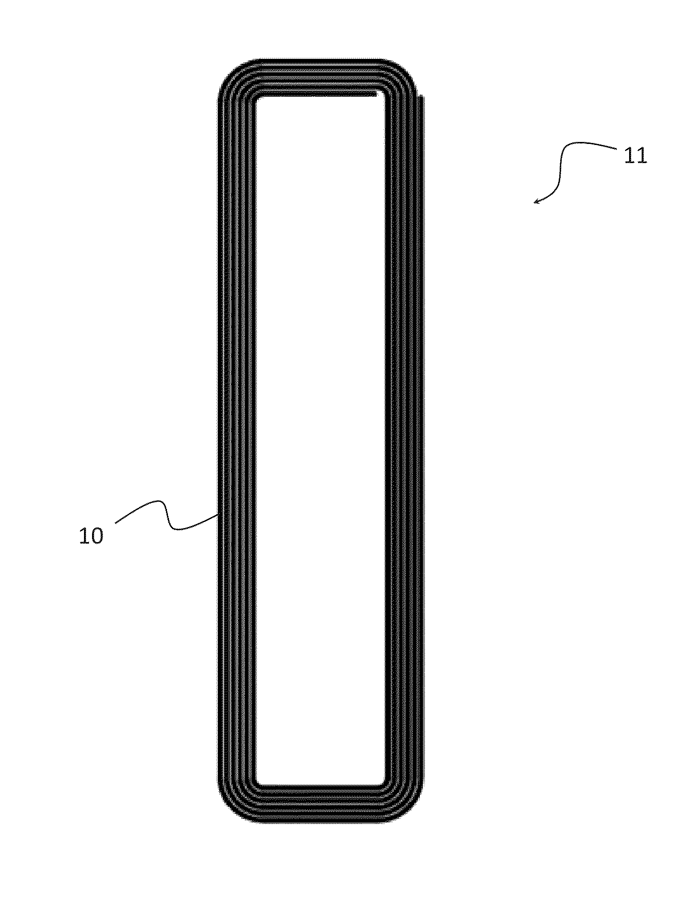
[0071]FIGS. 2A and 2B illustrate an embodiment of the current invention, a 13C-1H coil generally denoted by the reference numeral 11, where coil structures 10, 14 are placed on opposite sides of one dielectric substrate. Exemplary coil 11 would be appropriate to use as the inner coil pair in an NMR probe designed for detection of both 13C and 11H isotopes. In this embodiment, a dielectric substrate (not shown) separates two superconductive films patterned into self-resonant coil structures 10, 14. Two such films are disposed around a cylindrical sample as in the prior art to produce a uniform RF magnetic field across the sample. The long axis of coil 11 would be oriented along the field axis of the solenoidal NMR magnet.

[0072]The aspect of coil 11 distal to the sample can be seen in FIG. 2A and is patterned into spiral coil structure 10. Spiral coil structure 10 produces a field that is substantially perpendicular to the plane of the dielectric substrate. Spiral coil structure 10 is...

example 2

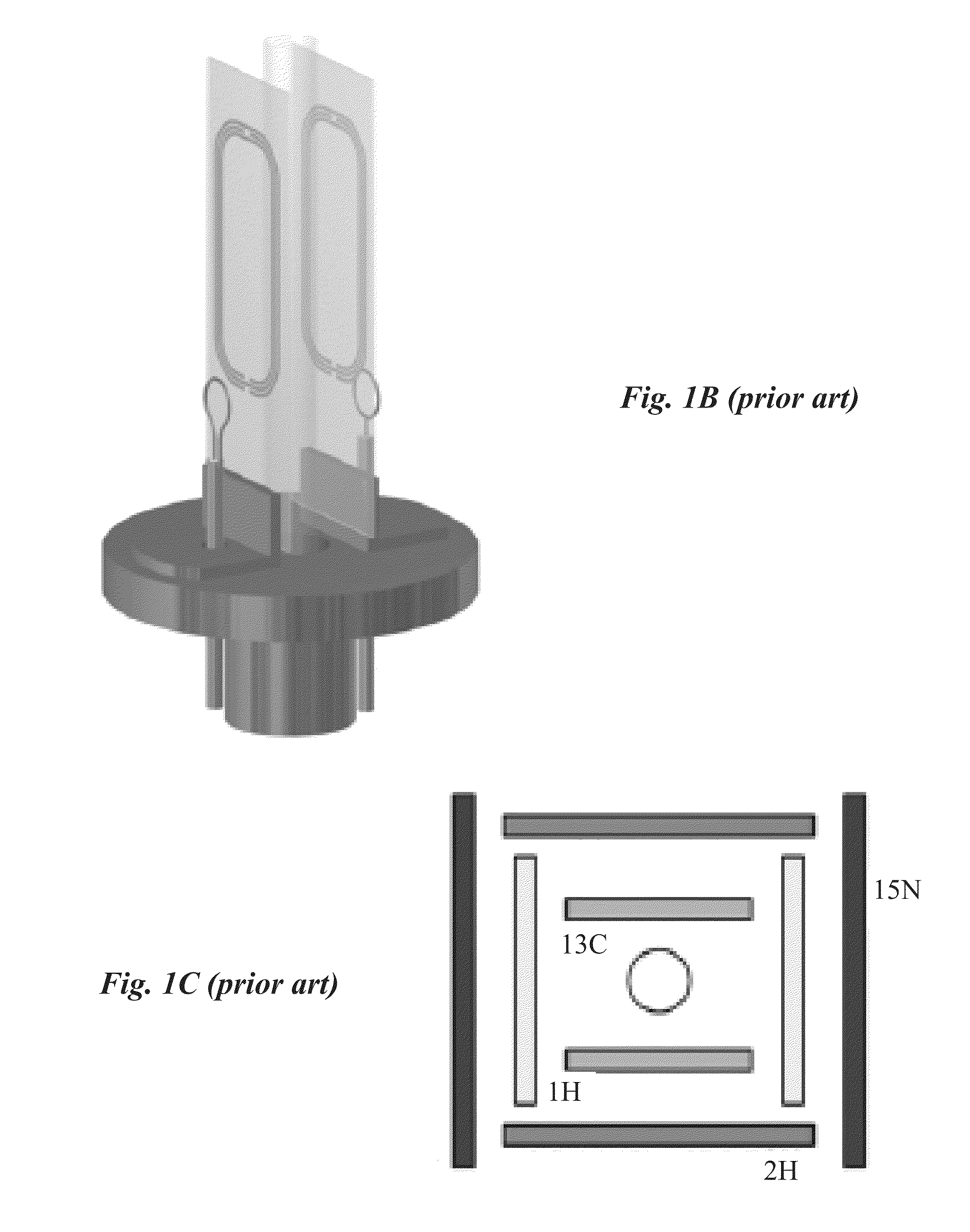
[0077]FIG. 3 illustrates another embodiment of the current invention, a 15N-2H coil generally denoted by the reference numeral 21, where the coil structures 22, 24 are positioned on the same side of one dielectric substrate and one coil is placed within the other coil. Exemplary coil 21 would be appropriate to use as the outer coil pair in an NMR probe designed for decoupling on the 15N channel and for engaging a 2H field frequency lock. In this embodiment, both self-resonant coil structures 22, 24 are patterned on the same side of the dielectric substrate, thereby eliminating the two-sided patterning of the HTS coils.

[0078]The longitudinal axis of coil 21 would be oriented along the field axis of the solenoidal NMR magnet. Coil 21 includes figure-8 coil structure 22 tuned to the 2H frequency and spiral coil structure 24 tuned to the 15N frequency. The magnetic field in the sample region at the spiral coil structure resonance frequency is substantially perpendicular to the dielectri...


PUM

PropertyMeasurementUnit
angleaaaaaaaaaa
nuclear magnetic resonance probeaaaaaaaaaa
magnetic fieldaaaaaaaaaa

Abstract

NMR probe coils designed to operate at two different frequencies, producing a strong and homogenous magnetic field at both the frequencies. This single coil, placed close to the sample, provides a method to optimize the NMR detection sensitivity of two different channels. In addition, the present invention describes a coil that generates a magnetic field that is parallel to the substrate of the coil as opposed to perpendicular as seen in the prior art. The present invention isolates coils from each other even when placed in close proximity to each other. A method to reduce the presence of electric field within the sample region is also considered. Further, the invention describes a method to adjust the radio-frequency tuning and coupling of the MAR probe coils.

Description

CROSS-REFERENCE TO RELATED APPLICATIONS[0001]This nonprovisional application is a continuation-in-part of and claims priority to U.S. nonprovisional application Ser. No. 13 / 916,231, entitled “NMR RF Probe Coil Exhibiting Double Resonance”, filed Jun. 12, 2013, which claims priority to provisional application No. 61 / 658,706, entitled “NMR RF Probe Coil Exhibiting Double Resonance”, filed Jun. 12, 2012, both of which are incorporated herein by reference.FEDERALLY SPONSORED RESEARCH OR DEVELOPMENT[0002]This invention was made with Government support under Grant No. 1R01EB009772-01 awarded by National Institute of Health through a subcontract from the University of Florida, Principal Investigators Arthur Edison. The government has certain rights in the invention.BACKGROUND OF THE INVENTION[0003]1. Field of the Invention[0004]This invention relates, generally, to nuclear magnetic resonance NMR). More specifically, it relates to radiofrequency (RE) transmit-receive coils.[0005]2. Brief De...

Claims


Application Information

Patent Timeline
Patent Type & Authority Patents(United States)
IPC IPC(8): G01V3/00G01R33/34G01R33/422G01R33/36G01R33/38
CPCG01R33/365G01R33/34023Y10T29/49155Y10T29/4913G01R33/3635G01R33/3802G01R33/3628G01R33/422G01R33/34061G01R33/62G01R33/38
Inventor BREY, WILLIAM W.EDISON, ARTHURRAMASWAMY, VIJAYKUMARHOOKER, JERRIS
Owner FLORIDA STATE UNIV RES FOUND INC
Why Eureka
Try Eureka