Friction welding of titanium aluminide turbine to titanium alloy shaft

a technology of titanium alloy shaft and friction welding, which is applied in the direction of machines/engines, non-electric welding apparatus, waterborne vessels, etc., can solve the problems of turbine lag, titanium-aluminide use, and undesirable phase transformation at the material interface of the material interface,

Active Publication Date: 2014-07-22
CATERPILLAR INC
View PDF18 Cites 5 Cited by
  • Summary
  • Abstract
  • Description
  • Claims
  • Application Information

AI Technical Summary

Problems solved by technology

However, turbocharger lag, which occurs while turbocharger turbines develop adequate rotational speed, can be a problem.
However, the use of titanium-aluminide can complicate joining of the turbine to the turbocharger shaft, which is often made with steel.
Titanium-aluminide and steel have different thermal expansion properties and may produce undesirable phase transformations at their material interfaces.
Therefore, because turbochargers experience significant temperature variations, a titanium-aluminide turbine and a steel shaft may be unsuitable for joining directly to one another.
Therefore, although this method may provide a suitable connection between the turbine and shaft, two welds must be made and an additional material must be used, which can add significant time and cost to production.
Further, use of a steel shaft adds significant weight to the turbocharger, which can increase turbocharger lag.
However, bonding a turbine made from a titanium aluminide to a shaft made from a titanium alloy is challenging because of three reasons: high local thermal stress involved with bonding process; formation of brittle intermetallic phases at the bonding interface; and inherent low room temperature ductility of titanium aluminide alloys.
Because of these reasons, the bonding interface between a titanium aluminide turbine and a titanium alloy shafts and even the titanium aluminide turbine itself are prone to crack during or after the bonding process.
In some applications, because of specific geometry or a large size of the titanium aluminide turbine, the local thermal stresses can become extremely high and therefore render the bonding process even more challenging.
This rapid change in geometry, in addition to the large thermal mass of turbine wheel, may cause a steep temperature gradient, and therefore, may cause large thermal stress which may exceed the strength of the titanium aluminide in the vicinity of the bonding interface with the titanium alloy shaft.
However, despite these recent advances, the joint between a titanium aluminide turbine and a titanium alloy shaft may crack during or after the joining process.
The friction welding process imposes substantial thermal stresses.
Because titanium aluminide and other intermetallic phases formed at the welding interface have a limited ductility, such components or joints can be prone to crack under stress.
Further, the stresses are often increased because of the geometry of the turbine and shaft and the size of the two components.
Thus, the joining of a titanium aluminide turbine to a titanium alloy shaft is very challenging.

Method used


Image

  • Friction welding of titanium aluminide turbine to titanium alloy shaft
  • Friction welding of titanium aluminide turbine to titanium alloy shaft
  • Friction welding of titanium aluminide turbine to titanium alloy shaft

Examples


Embodiment Construction

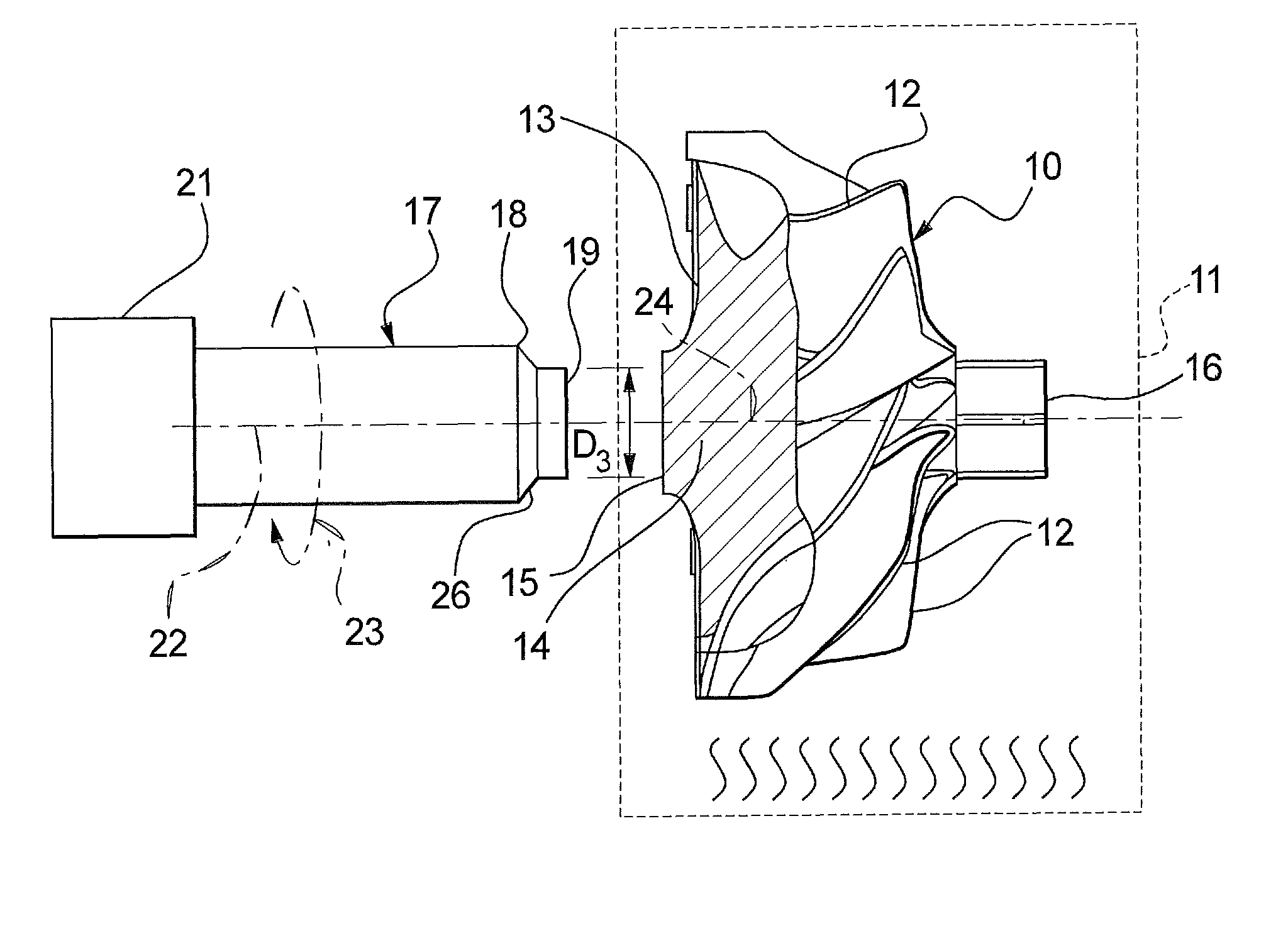
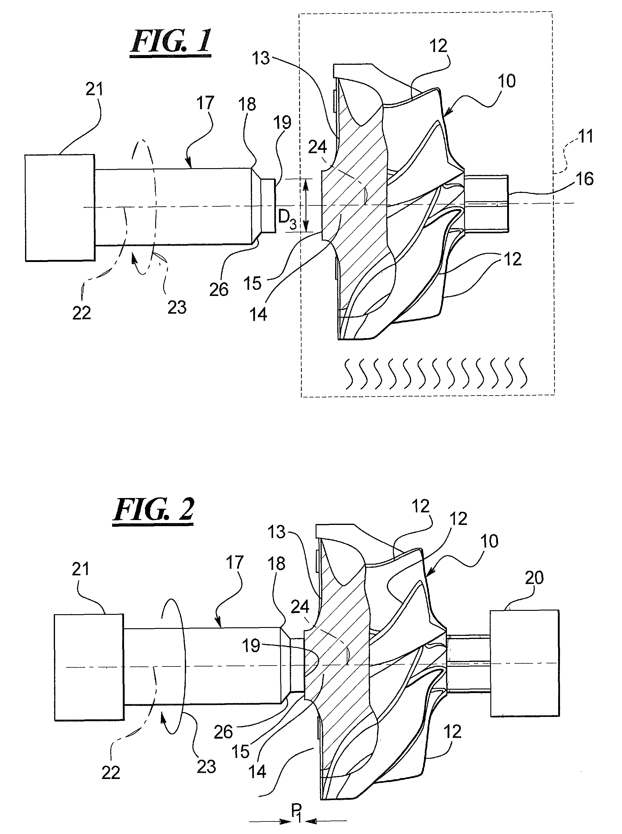
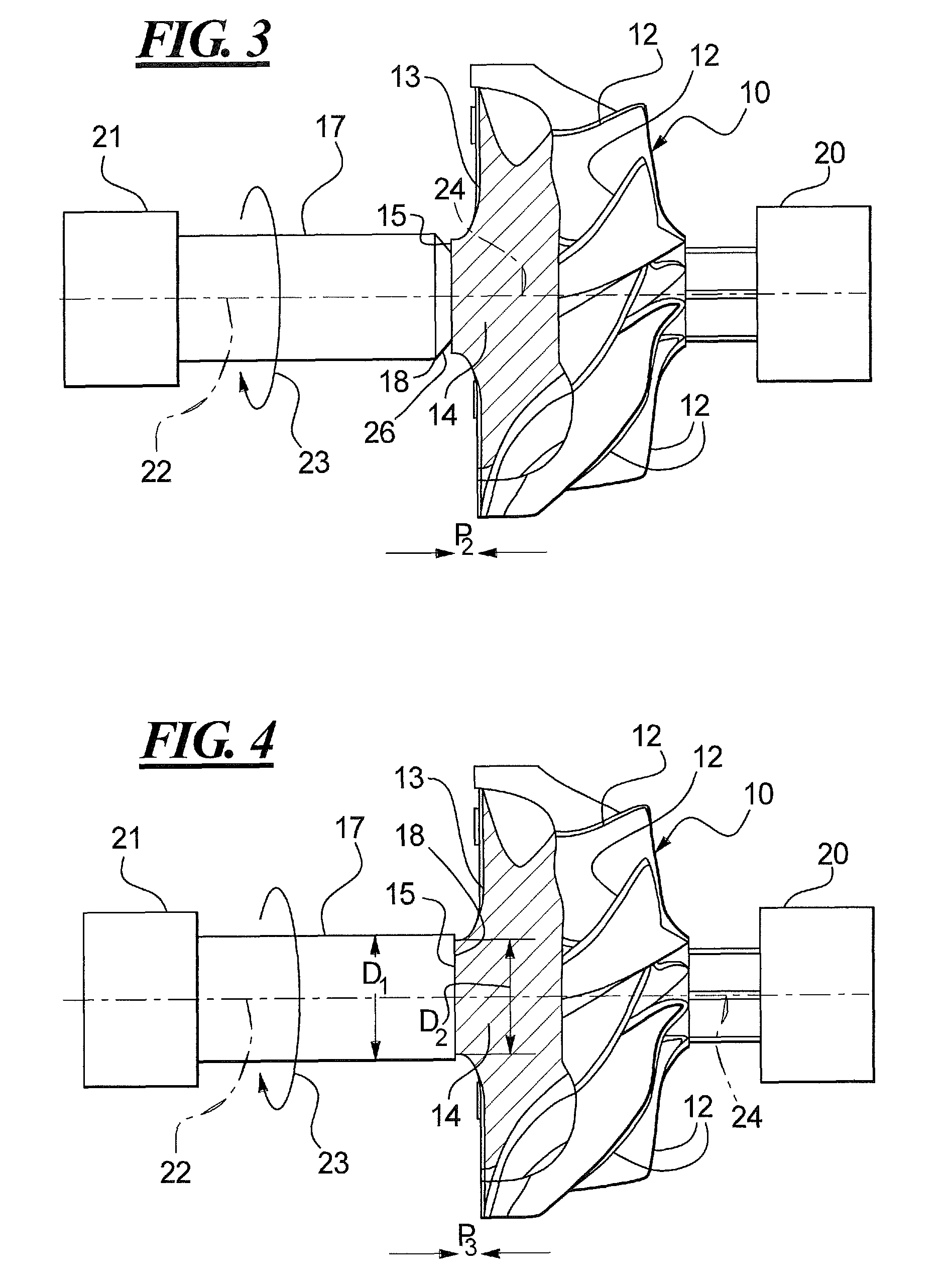
[0016]Referring to FIG. 1, a turbocharger turbine 10 is shown inside a heating apparatus 11 which may be used to preheat the turbine 10 prior to conducting the remaining steps of the disclosed frictional welding process. The turbine 10 may include a plurality of vanes 12 connected to a turbine rotor wheel 13. The rotor wheel 13 may include a hub portion 14 that features an end surface or welding surface 15. The turbine 10 may also include a distal extension 16 which may be used to hold the turbine 10 in place in the stationary chuck 17 shown schematically in FIG. 2.

[0017]Returning to FIG. 1, the shaft 17 may include an end 18 that is connected to a further distal end 19 by a beveled portion 26. The smaller distal end 19 engages the turbine 10 first during the frictional welding process as illustrated in FIG. 2. Still referring to FIG. 1, the shaft 17 may be held in a rotating chuck 21 that can rotate the shaft 17 about its axis 22 as indicated by the arrow 23. The axis 22 of the sha...


PUM

PropertyMeasurementUnit
temperatureaaaaaaaaaa

Abstract

A frictional welding process for joining a titanium aluminide turbine to a titanium alloy shaft is disclosed. The disclosed process includes preheating the turbine to a designated temperature, providing a specially-designed joining interface geometry at the distal end of the shaft and optimizing the frictional welding parameters. The frictional welding is carried out in multiple steps but, while the shaft is being spun by a rotating chuck, two different pressures and two different time periods are used until the narrower portions of the distal end of the shaft have been fused onto the welding surface of the turbine. Then, an additional forging step with yet another engagement pressure between the shaft and the turbine is carried out without rotation of the shaft.

Description

TECHNICAL FIELD[0001]This disclosure relates to turbochargers for engines, and more particularly, to turbochargers fabricated with titanium aluminide that are welded to shafts fabricated with titanium.BACKGROUND[0002]Turbochargers can increase the power of engines by providing additional air to the engine cylinders. An exhaust-gas driven turbine connected to a compressor may be used to produce the additional air. However, turbocharger lag, which occurs while turbocharger turbines develop adequate rotational speed, can be a problem. One method for reducing turbocharger lag is to decrease the weight of the turbocharger's rotating parts, including the turbine and the shaft attached to the turbine.[0003]Titanium-aluminide constitutes a lightweight, strong material that may be used to produce turbocharger turbines. However, the use of titanium-aluminide can complicate joining of the turbine to the turbocharger shaft, which is often made with steel. Titanium-aluminide and steel have diffe...

Claims


Application Information

Patent Timeline
Patent Type & Authority Patents(United States)
IPC IPC(8): F01D5/02
CPCF01D5/025B23K20/129B23K20/233B23K2203/24F05D2220/40F05D2230/239F05D2230/25F05D2300/174F05D2300/182B23K2103/24
Inventor YANG, NANJENSEN, JEFF A.CHAPA CABRERA, JESUS G.
Owner CATERPILLAR INC
Why Eureka
Try Eureka