Light source device, imaging apparatus and endoscope apparatus

a technology of light source and imaging apparatus, which is applied in the field of light source device, imaging apparatus and endoscope apparatus, can solve the problems of poor color rendering property, short intensity of light, and inability to obtain observation images peculiar to the specific wavelength band, and achieve high precision

Inactive Publication Date: 2014-07-29
FUJIFILM CORP
View PDF89 Cites 188 Cited by
  • Summary
  • Abstract
  • Description
  • Claims
  • Application Information

AI Technical Summary

Benefits of technology

[0016]With this light source device of (4), the light emitted from the first light source is irradiated onto phosphor, and then the white light is produced by the fluorescence emitted from the phosphor. Therefore, when a material of the phosphor or the type of the first light source is changed, a light intensity of a desired wavelength component can be easily designed, and the intended white light can be produced simply.
[0026]With this light source device of (9), the excitation light, which excites the phosphor to emit the light is eliminated on the optical path anterior to the phosphor. Therefore, the emission of the unnecessary light can be eliminated.
[0041]Furthermore, according to the endoscope apparatus of any of the above configurations, good observation images can be captured under plural types of illumination light, and thus it is possible to make the special light diagnosis with high precision.

Problems solved by technology

However, in this case, the illumination light runs short of an intensity of light around 450 to 480 nm and thus is poor in color rendering property as compared to a continuous spectrum, over a wavelength 430 to 680 nm, of an illumination light (Xe lamp), of the related art, for an endoscope.
However, as shown in FIG. 12B, under the illumination with in the special light, when the light in the specific wavelength band is light having a wavelength within the excitation wavelength band W, unnecessary fluorescence is emitted from the phosphor, and thus an observation image peculiar to the specific wavelength band might not be obtained.

Method used


Image

  • Light source device, imaging apparatus and endoscope apparatus
  • Light source device, imaging apparatus and endoscope apparatus
  • Light source device, imaging apparatus and endoscope apparatus

Examples


first embodiment

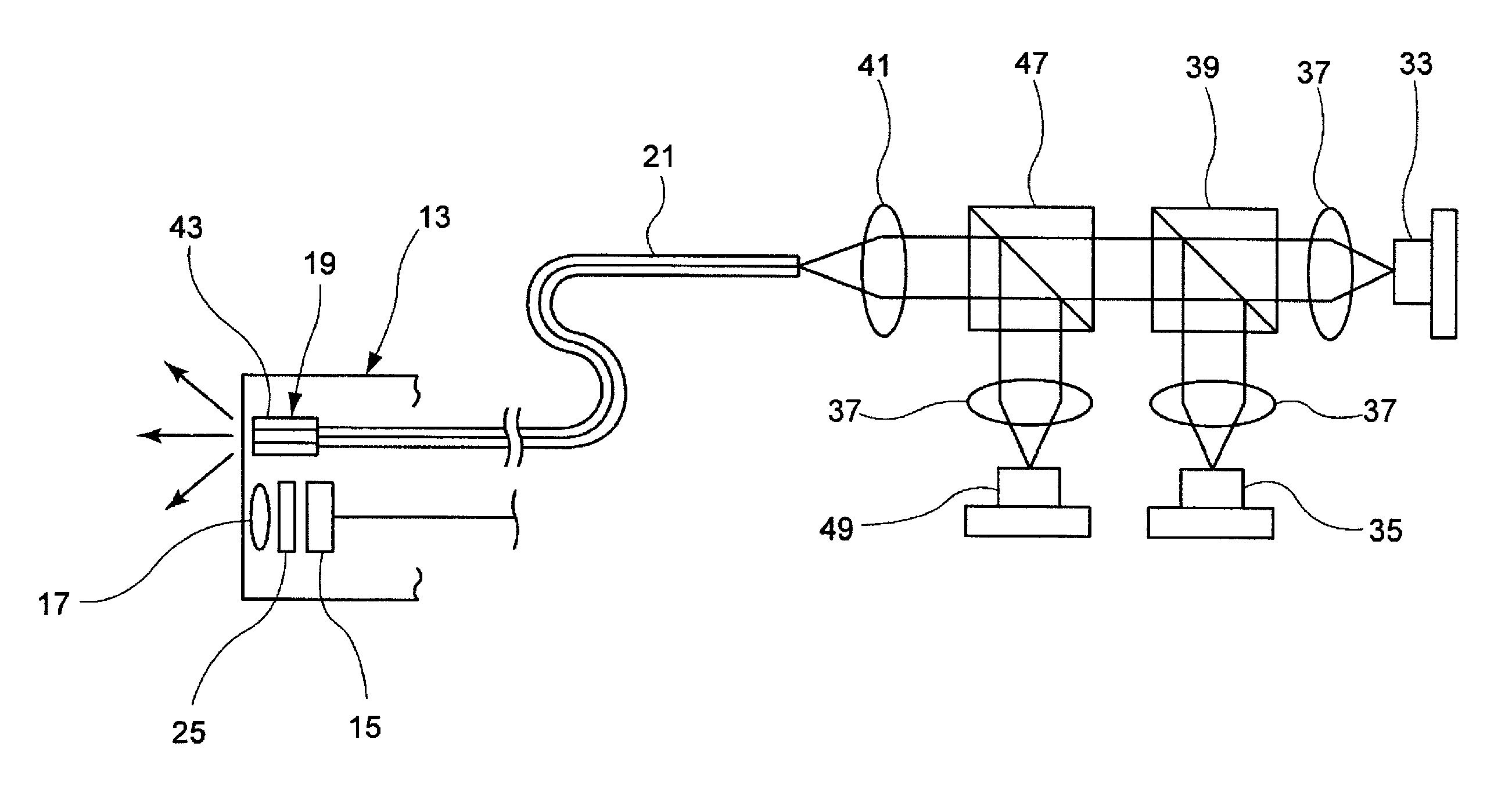
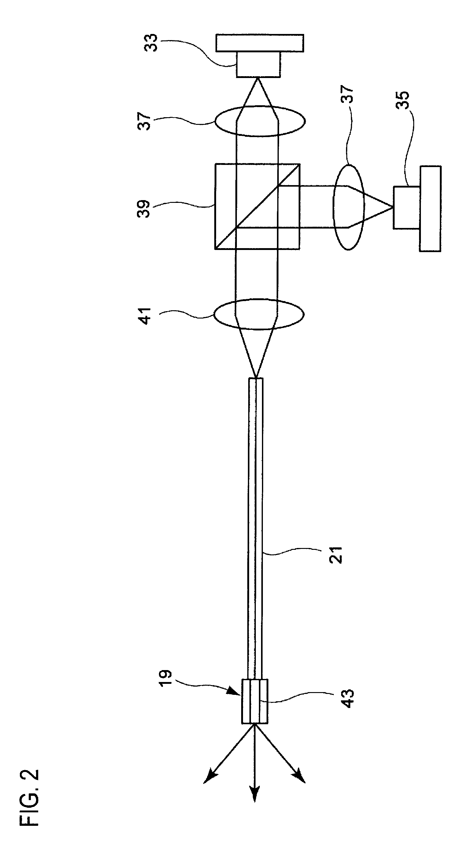
[0089]The green laser beam from the green laser light source 49 is coupled to the optical paths of the respective laser beams from the near-ultraviolet laser light source 33 and the blue laser light source 35, and then introduced into the optical fiber 21 via the converging lens 41. The phosphor 43 disposed on the light emission side of the optical fiber 21 is not excited by the introduced green laser beam, but is only excited by the near-ultraviolet laser beam from the near-ultraviolet laser light source 33 as in the

[0090]FIGS. 6A and 6B are graphs showing an excitation spectrum, an emission spectrum of a phosphor and spectral intensities of light from respective light sources under illumination with normal light (FIG. 6A) and under illumination with special light (FIG. 6B). As shown in FIG. 6A, in the normal light illumination in which the white light is irradiated, the white light is output from the phosphor 43, which is excited by the near-ultraviolet laser beam from the near-ul...

third embodiment

[0092]Next, a third embodiment that is configured so that the spectral characteristic of the imaging element is correlated with the light source wavelength of the illumination optical system will be described below.

[0093]The light source of this embodiment has basically the similar configuration to that in the first embodiment, but a relationship between the imaging element and the light source that excites the phosphor is defined in this embodiment.

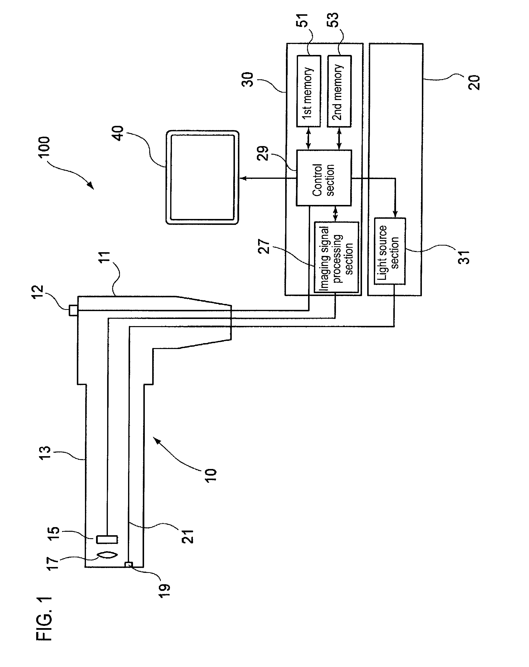
[0094]The imaging element 15 of this embodiment (see FIG. 1) has R (red), G (green), and B (blue) detection spectral characteristics as shown in FIG. 7. In this case, the spectral sensitivity for blue that is the detection color on the shortest wavelength side is set not to include the emission wavelength λ1 of the near-ultraviolet laser light source. As a result, the light emitted from the near-ultraviolet laser light source, which excites the phosphor 43 to emit light, is not detected by the imaging element 15.

[0095]That is, the emissi...

fourth embodiment

[0096]Next, a fourth embodiment including an unnecessary light cut filter for removing light used to excite the phosphor so as to emit fluorescence after the excitation light is irradiated onto the phosphor will be described below.

[0097]FIG. 8 is a configuration view showing still another optical system. Here, the same reference symbols are affixed to the same members as those shown in FIG. 5, and explanation thereon will be omitted or simplified.

[0098]In the imaging optical system of this embodiment, an unnecessary light cut filter 25 is disposed between the imaging element 15 and the imaging lens 17 of the endoscope insertion portion 13. The unnecessary light cut filter 25 is an optical filter having a spectral absorption characteristic shown in FIG. 9. That is, the unnecessary light cut filter 25 has such a characteristic that it absorbs the wavelength λ1 component of the light, which excites the phosphor 43 to emit light, and allows the light component of the wavelength longer t...


PUM


Abstract

A light source device includes a first light source, a second light source having an emission wavelength that is different from the first light source, and a phosphor that is disposed to be distant from the first light source and the second light source and absorbs light in a predetermined excitation wavelength band to emit fluorescence. The phosphor is disposed on an emission light optical path that is shared by the first light source and the second light source. The emission wavelength of the first light source is in the predetermined excitation wavelength band. The emission wavelength of the second light source is outside of the predetermined excitation wavelength band.

Description

CROSS-REFERENCE TO RELATED APPLICATIONS[0001]This application claims the benefit of Japanese Patent Application No. 2008-156032, filed Jun. 13, 2008, the entire contents of which are hereby incorporated by reference, the same as if set forth at length.BACKGROUND OF THE INVENTION[0002]1. Technical Field[0003]The invention relates to a light source device, an imaging apparatus and an endoscope apparatus.[0004]2. Description of the Related Art[0005]An endoscope apparatus that has been widely used is configured so that illumination light from a lamp that is provided in a light source device is guided by a light guide that is provided along an endoscope insertion portion, and the illumination light guided by this light guide is emitted from an illumination window that is provided at a front end of the endoscope insertion portion so as to illuminate an object site to be inspected. On the other hand, JP 2005-205195 A describes a light source device in which a blue laser beam is guided to a...

Claims


Application Information

Patent Timeline
Patent Type & Authority Patents(United States)
IPC IPC(8): A61B1/06A61B1/07
CPCA61B1/06A61B1/0638A61B1/0653A61B1/0661A61B1/07A61B1/05A61B1/063A61B5/0071A61B5/0084A61B5/0086A61B1/0655
Inventor SUNAGAWA, HIROSHIMIZUYOSHI, AKIRA
Owner FUJIFILM CORP
Why Eureka
Try Eureka