Device for determining a concentration of a constituent of blood in a hose line

a technology of blood hose and constituent, which is applied in the direction of color/spectral property measurement, sensors, medical devices, etc., can solve the problems of adverse effect on measurement accuracy, limited selection of light emitters, and reduced light yield of leds, so as to reduce the influence of hose line on the distance covered by light, the effect of reducing the signal amplitude and double the light yield

Inactive Publication Date: 2014-07-29
FRESENIUS MEDICAL CARE DEUTSCHLAND GMBH
View PDF14 Cites 14 Cited by
  • Summary
  • Abstract
  • Description
  • Claims
  • Application Information

AI Technical Summary

Benefits of technology

[0010]Since the two receiving elements for the hose line are moved towards one another by means of an electric motor, the required clamping force is applied uniformly. The electric-motor drive permits the adjustment of a specific feed rate at which the receiving elements are moved. It is thus possible to compress the hose line at an optimum feed rate, so that the hose line has the opportunity to centre itself exactly between the receiving elements. Jamming of the hose line due to an excessively rapid and non-uniform movement of the clamping elements is thus avoided.
[0011]Moreover, the device according to the present invention for determining the concentration of blood constituents is characterised by a monitoring unit, which is constituted such that the hose line inserted into the receiving elements can be detected. Automation of the measurement of the blood parameters is thus possible. For example, the measurement can be started not until and only when the hose line is inserted into the clamping unit. The light-emission period of the LEDs used as light emitters can thus be reduced, so that the service life of the LEDs is increased. Moreover, incorrect measurements are avoided when the hose line is not inserted.
[0017]A particularly preferred embodiment provides a transition section between the plane contact faces and the semi-cylindrical contact faces of the two receiving elements, said transition section being constituted such that the inner plane contact faces are transformed continuously into the outer semi-cylindrical contact faces. A continuous transition is understood to mean any transition which permits a uniform deformation of the hose line, so that the circular cross-section of the hose line is transformed uniformly into the square cross-section and the hose line is not kinked.
[0018]The uniform transition from the circular to the square cross-section not only has the advantage that the hose line is protected when the clamping unit is closed, but also the advantage that turbulent currents are avoided during the transition from the round to the square line cross-section. The length of the square measuring channel, in which light emitters and light detectors are disposed, can thus be kept as small as possible. Shortening of the measuring channel in turn leads to small closing forces, which is also advantageous.
[0021]The use of two light emitters instead of only one light emitter for coupling light into the hose line has the advantage that the light yield of the LEDs is doubled, whereas the influence of the hose line on the distance covered by the light is reduced.
[0023]The combination of two light emitters disposed on opposite sides of the hose line to form a group doubles the light yield. Since the light of the two light emitters is evaluated on different measurement sections, the influences of the hose line are averaged out, as a result of which the measurement accuracy is increased.

Problems solved by technology

It is a drawback that the signal amplitude diminishes with an increasing distance between light emitter and light detector.
This however considerably limits the selection of the components available as light emitters.
A smaller distance between light emitters and light detectors, which does not necessitate an increase in the intensity of the radiation, on the other hand has an adverse effect on the accuracy of the measurement.
In addition, there are variations in the hose wall thickness, which cannot be ruled out on short sections of the hose lines with the known extrusion processes for the production of hose lines.

Method used


Image

  • Device for determining a concentration of a constituent of blood in a hose line
  • Device for determining a concentration of a constituent of blood in a hose line
  • Device for determining a concentration of a constituent of blood in a hose line

Examples


Embodiment Construction

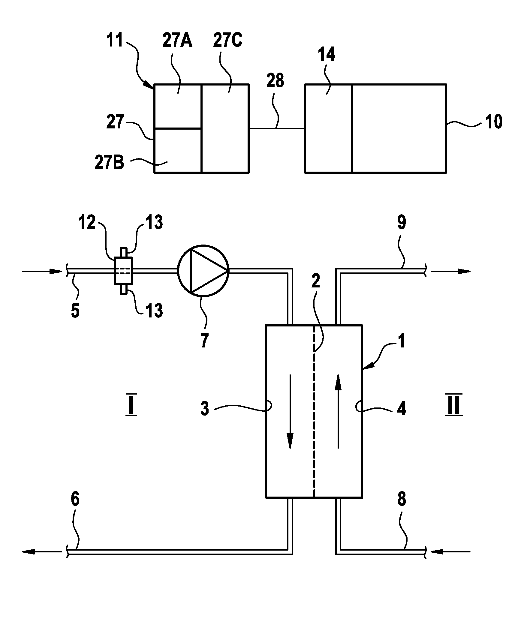
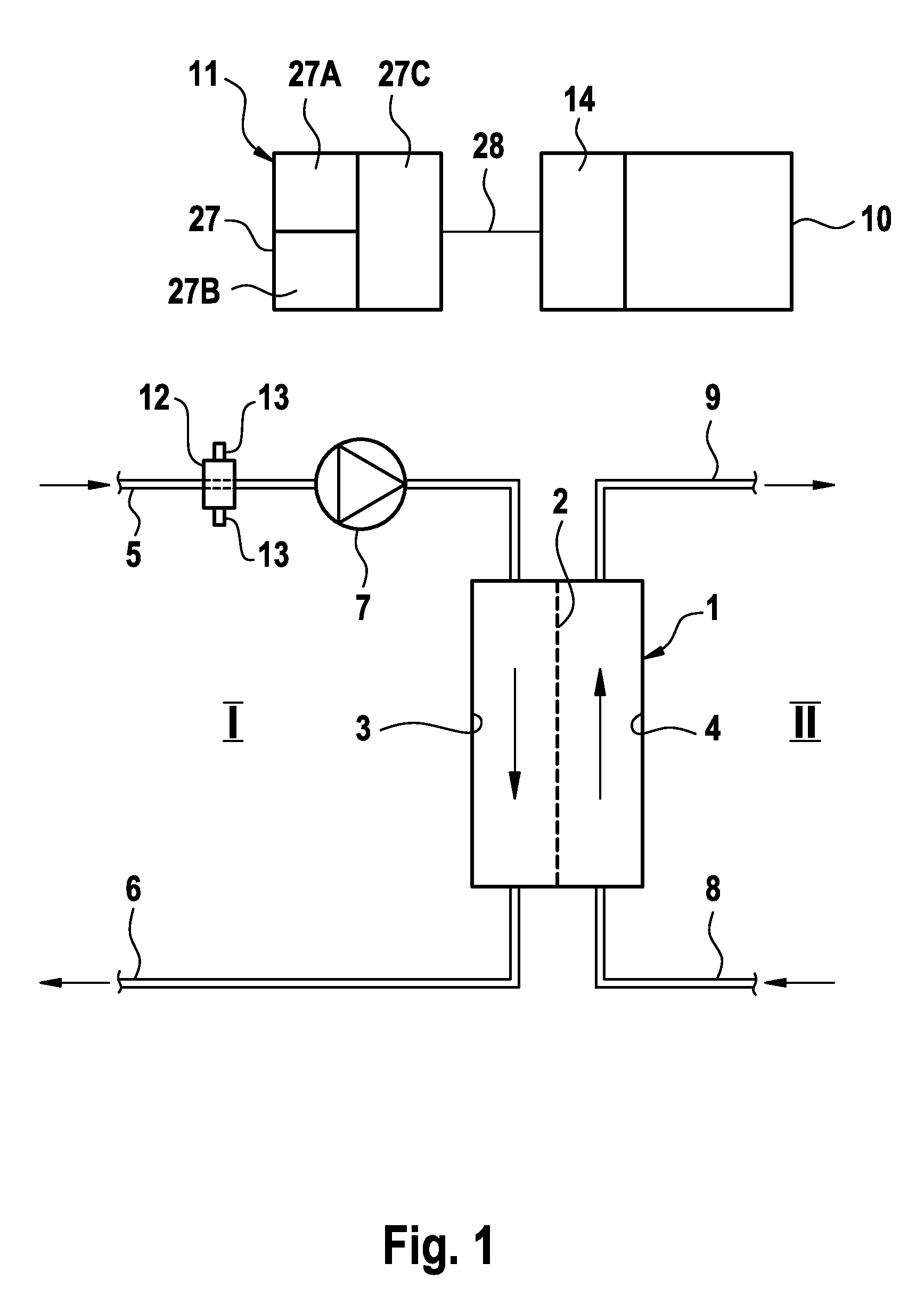
[0039]FIG. 1 shows only the components of an apparatus for extracorporeal blood treatment that are essential to the present invention, in a very simplified diagrammatic representation. The extracorporeal blood treatment apparatus, for example a dialysis apparatus, comprises a dialyser or filter 1, which is divided by a semipermeable membrane 2 into a blood chamber 3 and a dialysing fluid chamber 4. An arterial blood line 5 leads from the patient to blood chamber 3, whilst a venous blood line 6 leads away from the blood chamber 3 and to the patient. A blood pump 7 disposed in arterial blood line 5 conveys the blood in extracorporeal blood circuit I. Dialysing fluid system II of the dialysis apparatus is represented only in outline. It comprises a dialysing fluid supply line 8 leading to dialysing fluid chamber 4 and a dialysing fluid discharge line 9 leading away from dialysing fluid chamber 4. Arterial and venous blood lines 5, 6 are hose lines which are at least partially permeable...


PUM

PropertyMeasurementUnit
angleaaaaaaaaaa
angleaaaaaaaaaa
currentaaaaaaaaaa

Abstract

A device for determining the concentration of a constituent of blood in a hose line, in particular in the hose line of an extracorporeal blood circuit of an extracorporeal blood treatment apparatus, includes a clamping unit having an actuation mechanism configured to apply a clamping force such that first and second receiving elements are moved towards one another from a first position releasing the hose line into a second position clamping the hose line, in which the drive of the actuation mechanism takes place with an electric motor, and a monitoring unit configured to detect a hose line inserted into the receiving elements. A method for detecting a hose line in a clamping unit of a device for determining the concentration of a blood constituent in the hose line is also described. Automation of the measurement of the blood parameters is thus possible.

Description

CROSS-REFERENCES TO RELATED APPLICATIONS[0001]The present application claims priority to U.S. Provisional Application No. 61 / 510,104, filed on Jul. 21, 2011, and claims priority to Application No. DE 10 2011 108 050.7, filed in the Federal Republic of Germany on Jul. 21, 2011, each of which is expressly incorporated herein in its entirety by reference thereto.FIELD OF INVENTION[0002]The present invention relates to a device for determining the concentration of a constituent of blood in a hose line, in particular in the hose line of an extracorporeal blood circuit of an extracorporeal blood treatment apparatus. Moreover, the present invention relates to a method for detecting a hose line, in particular a hose line of an extracorporeal blood circuit of an extracorporeal treatment apparatus, in a clamping unit of a device for determining the concentration of a blood constituent in the hose line.BACKGROUND INFORMATION[0003]Various methods are known for determining the concentration of s...

Claims


Application Information

Patent Timeline
Patent Type & Authority Patents(United States)
IPC IPC(8): G01N33/48
CPCG01N33/49A61B5/14557A61M1/367A61M2205/14A61M2205/3306A61M2230/20G01N21/05G01N21/31G01N2021/0378G01N2021/3144
Inventor ZHANG, WEISCHULTE, ELKEKAISER, MARTINMUELLER, CARSTENKLEIN, TOMZERLE, STEFANBARDORZ, CHRISTOPHSTUEHLER, STEFAN
Owner FRESENIUS MEDICAL CARE DEUTSCHLAND GMBH
Why Eureka
Try Eureka