
Liquid chromatograph

a liquid chromatograph and chromatograph technology, applied in the field of liquid chromatographs, can solve the problems of affecting the carry-over performance of the autosampler, and the problem of the part of the sample remaining in the small clearance between the needle and the needle seal becoming more pronounced

Active Publication Date: 2014-08-05
SHIMADZU CORP
View PDF42 Cites 9 Cited by
  • Summary
  • Abstract
  • Description
  • Claims
  • Application Information

AI Technical Summary

Benefits of technology

The present invention aims to prevent carry-over in high-speed liquid chromatographs caused by residual sample in the injection port. The invention reduces the pressure applied on the joint section between the needle and the injection port by reducing the solution sending flow rate of the mobile phase, to remove the sample from the injection port. The invention also optimizes the time for which the solvent delivery pump operates at a second flow rate after the sample is sucked into the sample loop through the injection needle, to prevent the sample from remaining in the injection port and contaminating the analysis results. The injection port is directly incorporated in the flow path switching valve to reduce dead volume and further enhance the effect of preventing sample carry-over. The invention is advantageous in analyzing samples using high-resolution columns with small particle diameters.

Problems solved by technology

If this contamination occurs, it affects carry-over performance of the autosampler for the high-speed liquid chromatograph.
The problem of the part of the sample remaining in the small clearance between the needle and the needle seal becomes more pronounced on an analysis condition of high solution sending pressure of the mobile phase, such as when a high-separation column having a particle diameter of packing material of 2 μm or smaller is used as a separation column of the analytical flow path.

Method used


Image

  • Liquid chromatograph
  • Liquid chromatograph
  • Liquid chromatograph

Examples


Embodiment Construction

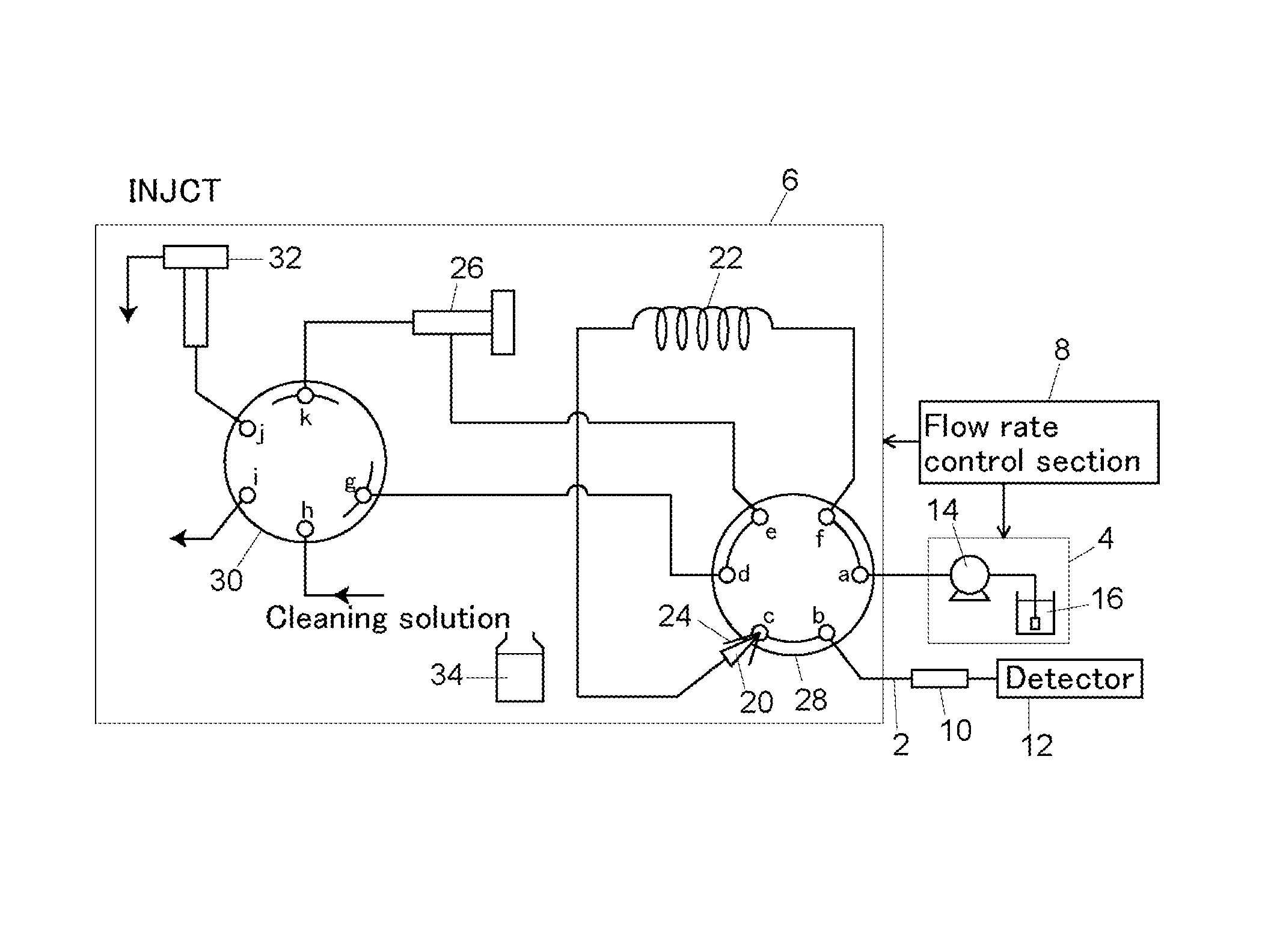
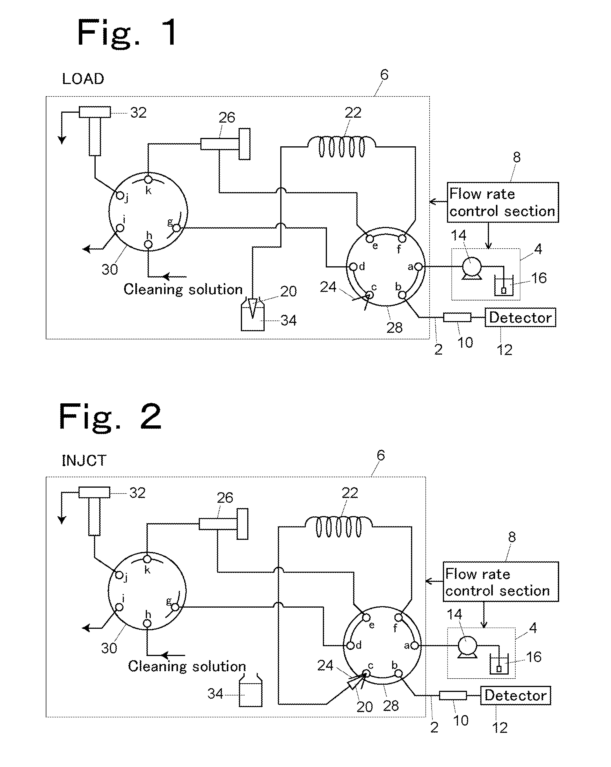
[0039]FIG. 1 shows the high-speed liquid chromatograph in an example in a sample sucking mode (LOAD). The high-speed liquid chromatograph includes an analytical flow path 2, a mobile phase sending section 4, an autosampler 6, and a flow rate control section 8.

[0040]The analytical flow path 2 includes an analytical column 10 disposed on a flow path of a mobile phase to separate an introduced sample into components and a detector 12 for detecting components of the sample separated by the column 10. As the detector 12, an ultraviolet absorptiometer or a mass spectrometer may be used.

[0041]The mobile phase sending section 4 supplies the mobile phase 16 in a mobile phase vessel with a solvent delivery pump 14.

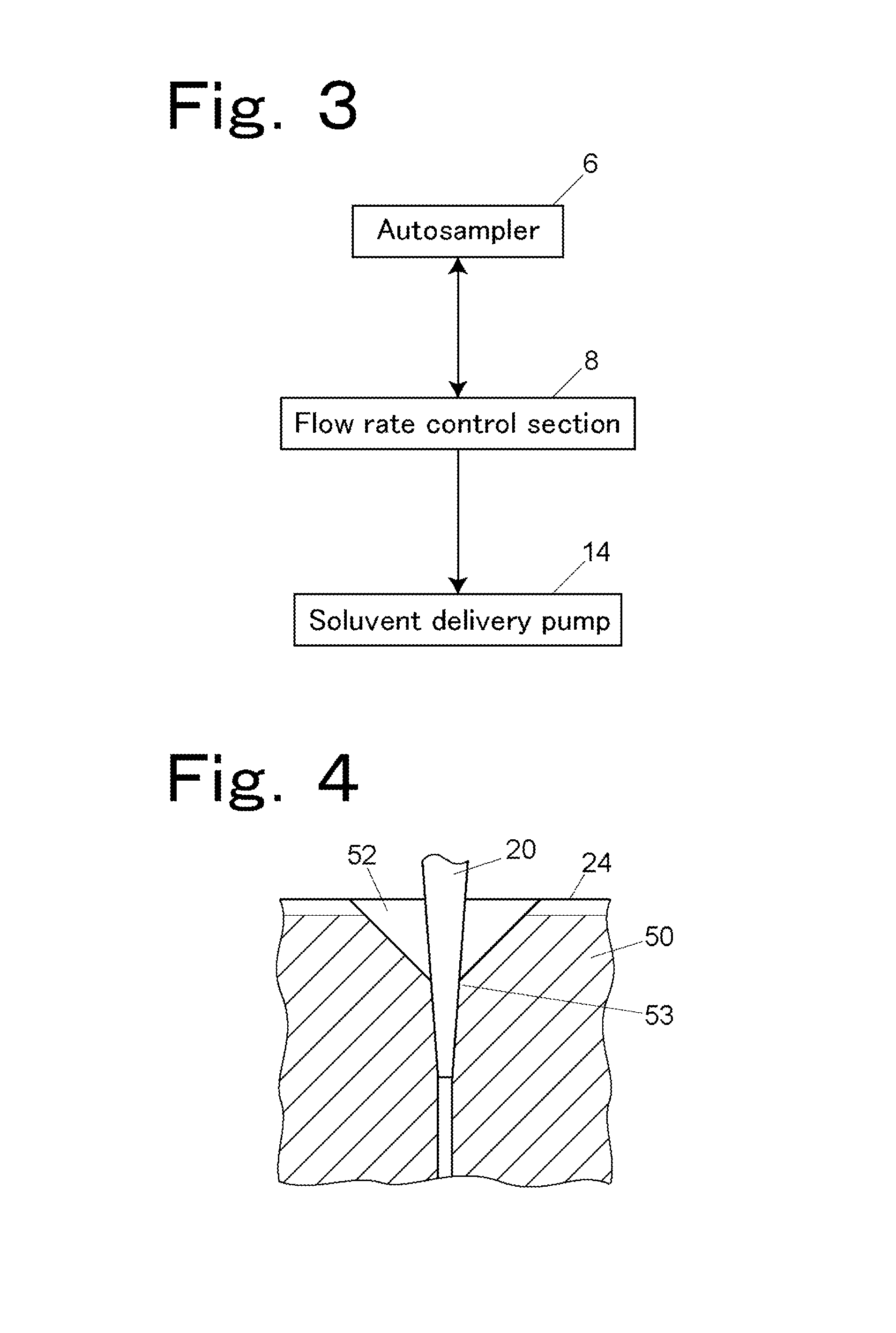
[0042]The autosampler 6 includes an injection needle 20, a sample loop 22, an injection port 24, a metering pump 26, and a flow path switching valve 28.

[0043]The injection needle 20 is connected to a tip end of the sample loop 22. The injection needle 20 is retained on a transfer me...


PUM

PropertyMeasurementUnit
particle diameteraaaaaaaaaa
liquidaaaaaaaaaa
flow rateaaaaaaaaaa

Abstract

In injecting a sample sucked into a sample loop in an autosampler from an injection needle into an analytical flow path via an injection port by a mobile phase, a sending flow rate of the mobile phase is reduced from a certain flow rate determined in an analysis condition to reduce pressure applied on a joint section between the needle and the injection port to thereby reduce the sample remaining in the injection port.

Description

BACKGROUND OF THE INVENTION[0001]1. Field of the Invention[0002]The present invention relates to a liquid chromatograph including a high-speed liquid chromatograph and particularly to a liquid chromatograph including an autosampler for injecting a sample by a whole quantity injection system.[0003]2. Description of the Related Art[0004]Sample injection systems of the autosampler for the high-speed liquid chromatograph can be broadly divided into two systems, i.e., a loop injection system for injecting part of a sucked sample into an analytical flow path after filling it in a sample loop and a whole quantity injection system for injecting the whole quantity of a sucked sample into an analytical flow path as it is. The whole quantity injection system is a method by which the sample is less contaminated than by the loop injection system.[0005]In the loop injection system, an injection needle is not connected to the sample loop, and the injection needle is connected to a sucking pump to ...

Claims


Application Information

Patent Timeline
Patent Type & Authority Patents(United States)
IPC IPC(8): G01N13/00G01N30/20G01N30/24G01N30/32
CPCG01N30/24G01N30/32G01N30/20
Inventor MAEDA, YOSHIAKI
Owner SHIMADZU CORP
Learn More