EGR control apparatus for internal combustion engine

a control apparatus and internal combustion engine technology, applied in the direction of electrical control, process and machine control, instruments, etc., can solve the problems of increased exhaust emissions, unstable combustion state of the engine, short or excessive inert gas supplied to the cylinders, etc., to improve operability, reduce exhaust emissions, and stable combustion state

Active Publication Date: 2014-08-05
HONDA MOTOR CO LTD
View PDF22 Cites 14 Cited by
  • Summary
  • Abstract
  • Description
  • Claims
  • Application Information

AI Technical Summary

Benefits of technology

[0007]It is an object of the present invention to provide an EGR control apparatus for an internal combustion engine, which is capable of properly controlling an inert gas amount of two types of EGR gas supplied to cylinders of the engine via two paths different from each other, thereby making it possible to ensure a stable combustion state and reduced exhaust emissions, and improve operability.
[0010]In contrast, according to this EGR control apparatus, the first EGR gas amount and the second EGR gas amount are controlled such that when the combination of the load represented by the load parameter and the engine speed is in the predetermined region, the first inert gas amount which is the amount of inert gas in the first EGR gas supplied to the cylinders exceeds the second inert gas amount which is the amount of inert gas in the second EGR gas supplied to the cylinders. Therefore, if the predetermined region is set to such a region that a large amount of low-temperature inert gas is required so as to lower the in-cylinder gas temperature or the compression end temperature, e.g. a region of high engine speed and high load, it is possible to supply, in such a region, a large amount of a lower-temperature one of the first inert gas and the second inert gas to the cylinders, whereby it is possible to lower the in-cylinder gas temperature and the compression end temperature.
[0011]In addition, the first EGR gas amount and the second EGR gas amount are controlled such that as the engine speed is higher or the load represented by the load parameter is larger, the first inert gas amount more exceeds the second inert gas amount. Therefore, as the degree of demand of lower-temperature inert gas is higher because of the engine speed being higher or the load being larger, it is possible to appropriately supply a larger amount of low-temperature inert gas to the cylinders in accordance therewith. Further, under a high-engine speed condition or a high-load condition, the amount of intake air to the cylinders increases and time taken for gases in the intake passage to be conveyed to the cylinders is reduced, and hence it is possible to speedily supply the first inert gas and the second inert gas to the cylinders. With the above configuration, it is possible to appropriately control the amount of inert gas in the EGR gas supplied to the cylinders according to the degree of demand of low-temperature inert gas. This makes it possible to secure a stable combustion state, reduce exhaust emissions, and improve operability (throughout the specification, “detection” as in “detection of the engine speed” and “detection of the load parameter” is by no means limited to direct detection of these parameters, but includes calculation of values thereof, and “supply of part of burned gases to the cylinders via a short path” includes causing part of burned gases to remain in combustion chambers of the cylinders without discharging the part out of the combustion chambers, and “inert gas amount” and “EGR amount” includes a flow rate of inert gas and a flow rate of EGR gas, respectively.)
[0014]The second EGR device supplies the second EGR gas to the cylinders via a shorter path than the first EGR device supplies the first EGR gas to the cylinders, and has characteristics of shorter dead time and higher responsiveness than the first EGR device. Therefore, even when the rate of convergence of the second difference to 0 is set to be higher than the rate of convergence of the first difference to 0, the first EGR device and the second EGR device can positively realize such convergence rates because of the difference in responsiveness therebetween, whereby it is possible to prevent the control of the first EGR device by the first EGR control means and the control of the second EGR device by the second EGR control means from interfering with each other. In addition to this, it is possible for the second EGR device, which is high in responsiveness, to accurately supply an amount of inert gas which cannot be secured by the first EGR device alone, which is low in responsiveness. For the reasons described above, it is possible to secure a stable combustion state and reduced exhaust emission, and improve operability.
[0016]With the configuration of the preferred embodiment, using the predetermined response-designating control algorithms, the first EGR control input and the second EGR control input are calculated, respectively, such that the first difference and the second difference converge to 0. Therefore, it is possible to cause the first difference and the second difference to converge to 0 by exponential behaviors. This makes it possible to further improve the stability of the combustion state, further reduce exhaust emissions, and further improve operability.

Problems solved by technology

However, when the amount of the EGR gas is controlled without taking the above fact into account, as in the EGR control apparatus disclosed in Japanese Laid-Open Patent Publication (Kokai) No. 2004-150319, the amount of inert gas supplied to the cylinders becomes short or excessive, which can make the combustion state of the engine unstable or result in increased exhaust emissions.

Method used


Image

  • EGR control apparatus for internal combustion engine
  • EGR control apparatus for internal combustion engine
  • EGR control apparatus for internal combustion engine

Examples


first embodiment

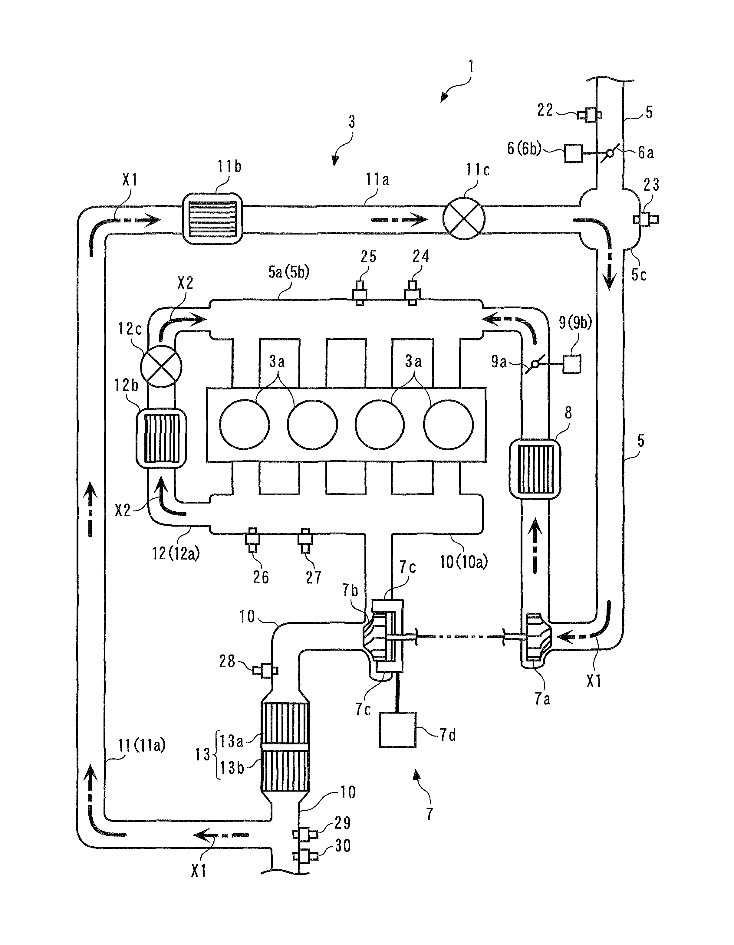
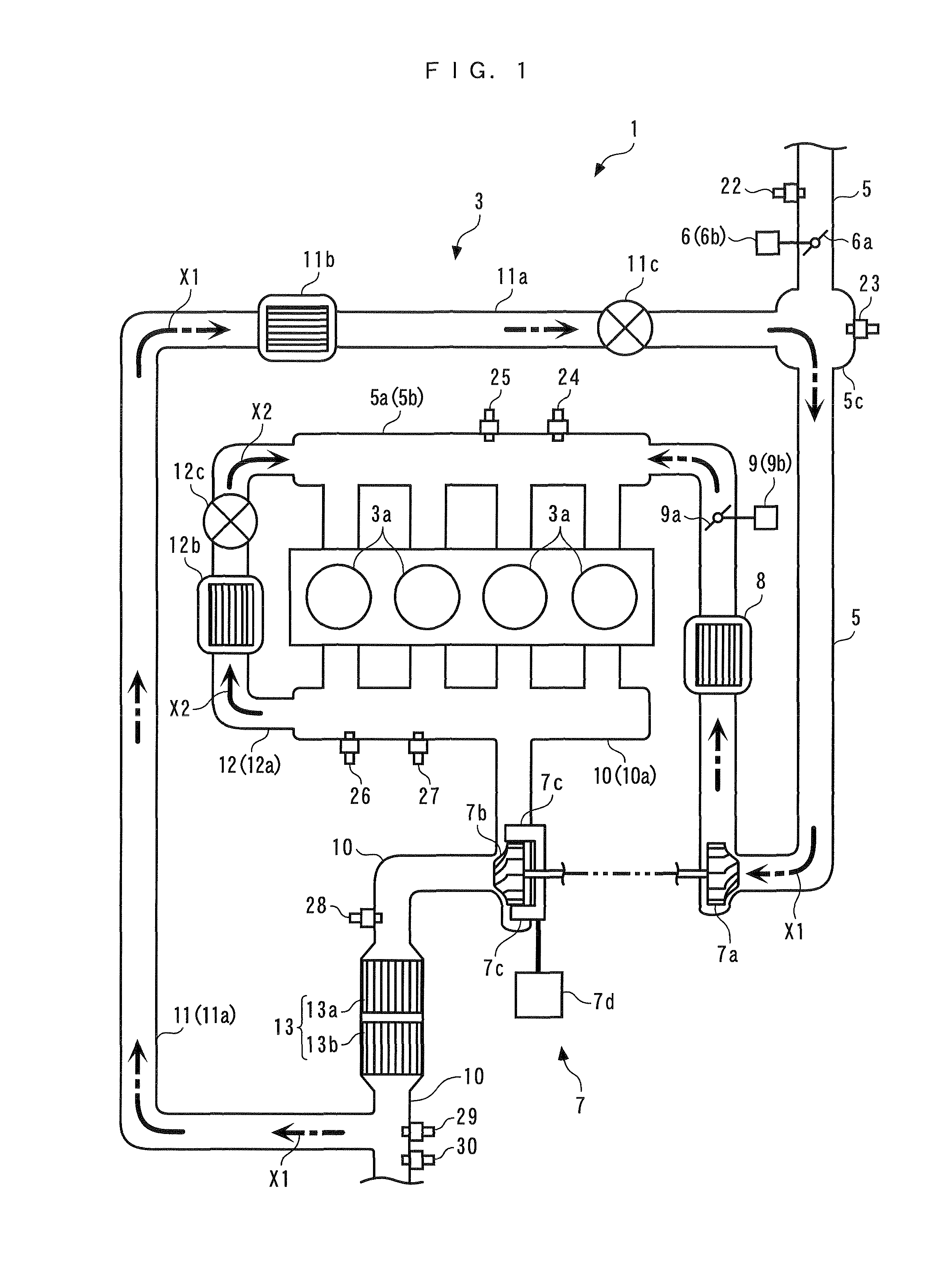
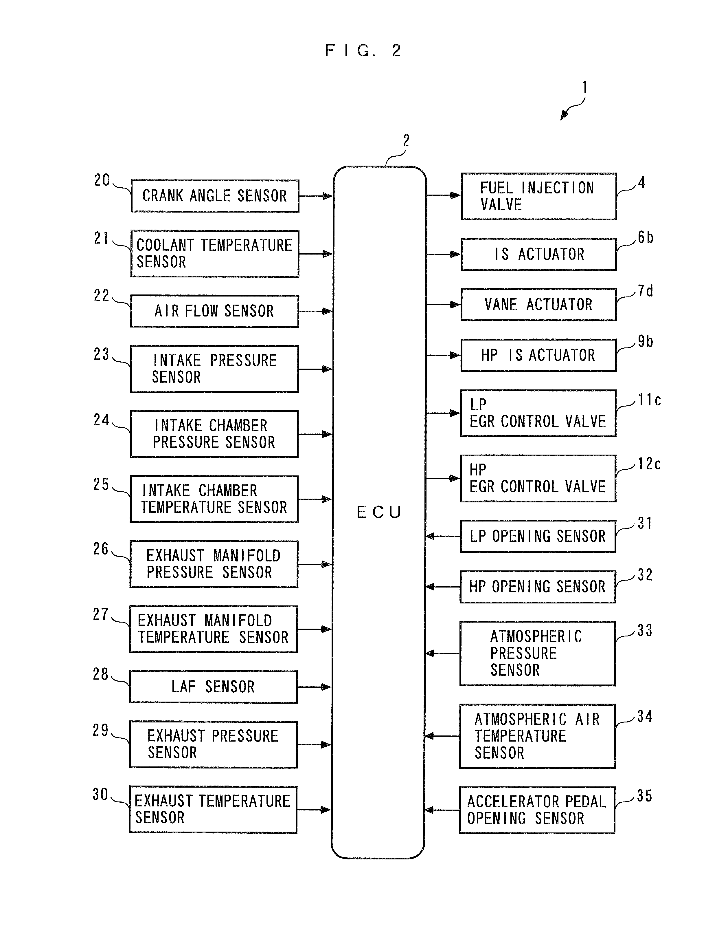
[0049]The invention will now be described in detail with reference to the drawings showing preferred embodiments thereof. Referring to FIG. 2, an EGR control apparatus 1 for an internal combustion engine, according to the present invention, includes an ECU 2. As will be described hereinafter, the ECU 2 controls the internal combustion engine (hereinafter simply referred to as “the engine”) 3 shown in FIG. 1.

[0050]The engine 3 is a diesel engine that is installed on a vehicle, not shown, as a motive power source. The engine 3 is equipped with four cylinders 3a and fuel injection valves 4 (only one of which is shown in FIG. 2) provided for the respective cylinders 3a. The fuel injection valves 4 are electrically connected to the ECU 2, and the opening and closing timing of each fuel injection valve 4 is controlled by a control input signal from the ECU 2, whereby the fuel injection amount and fuel injection timing of the fuel injection valve 4 are controlled.

[0051]The engine 3 is prov...

second embodiment

[0452]Although in the second embodiment, the hierarchical neural network is employed as a neural network, by way of example, this is not limitative, but in the present invention, a mesh neural network, an RBF (radial basis function) neural network, a chaos neural network, a recurrent neutral network, and so forth may be used as the neural network.

[0453]Further, in the elements of the inputs Ub, Uc, Ud, and Ue shown in the respective equations (156), (166), (176), and (186), a value corresponding to the operation amount of the vane actuator 7d, i.e. the vane opening αtb may be used in place of the chamber gas flow rate dGgas_CP.

[0454]Further, also in the second embodiment, the error EVNS may be calculated by the aforementioned equation (131), and the low-pressure inert gas ratio RLP may be calculated by the aforementioned equation (136).


PUM


Abstract

An EGR control apparatus for an internal combustion engine, which is capable of properly controlling an inert gas amount of two types of EGR gas supplied to cylinders of the engine via two paths different from each other, thereby making it possible to ensure a stable combustion state, reduced exhaust emissions, and improve operability. The EGR control apparatus includes low-pressure and high-pressure EGR devices, and an ECU. The ECU controls the low-pressure and high-pressure EGR gas amounts according to engine speed and demanded torque, and when a combination of engine speed and demanded torque is in a predetermined region, the low-pressure and high-pressure EGR gas amounts are controlled such that inert gas in low-pressure EGR gas exceeds in amount inert gas in high-pressure EGR gas, and the former more exceeds the latter as engine speed is higher or demanded torque is larger.

Description

BACKGROUND OF THE INVENTION[0001]1. Field of the Invention[0002]The present invention relates to an EGR control apparatus for an internal combustion engine, which controls the amounts of two types of EGR gas in the engine in which the two types of EGR gas are supplied to cylinders thereof via two paths different from each other.[0003]2. Description of the Related Art[0004]Conventionally, as an EGR control apparatus for an internal combustion engine, one disclosed in Japanese Laid-Open Patent Publication (Kokai) No. 2004-150319 is known. This engine is a diesel engine, and is provided with a turbocharger, a low-pressure EGR device, a high-pressure EGR device, and so forth. The low-pressure EGR device recirculates part of exhaust gases from an exhaust passage on the downstream side of a turbine of the turbocharger and a catalytic device into an intake passage on the upstream side of a compressor of the turbocharger, as low-pressure EGR gas, while the high-pressure EGR device recircula...

Claims


Application Information

Patent Timeline
Patent Type & Authority Patents(United States)
IPC IPC(8): F02B47/08F02M25/07
CPCF02D41/005F02M25/0707F02M25/0709F02M25/0726Y02T10/47F02M26/05F02M26/06F02M26/22Y02T10/40
Inventor YASUI, YUJIHASHIMOTO, EIJIHAGA, HISAONAKAJIMA, KOICHI
Owner HONDA MOTOR CO LTD
Why Eureka
Try Eureka