Control device for internal combustion engine

Active Publication Date: 2017-09-21
HITACHI ASTEMO LTD
View PDF1 Cites 2 Cited by
  • Summary
  • Abstract
  • Description
  • Claims
  • Application Information

AI Technical Summary

Benefits of technology

[0010]According to the present invention, it is possible to provide an internal combustion engine control dev

Problems solved by technology

In addition, if the recirculating exhaust gas amount reaches a certain level, the combustion becomes unstable.
For this reason, if the recirculating exhaust gas amount is determin

Method used


Image

  • Control device for internal combustion engine
  • Control device for internal combustion engine
  • Control device for internal combustion engine

Examples


example 1

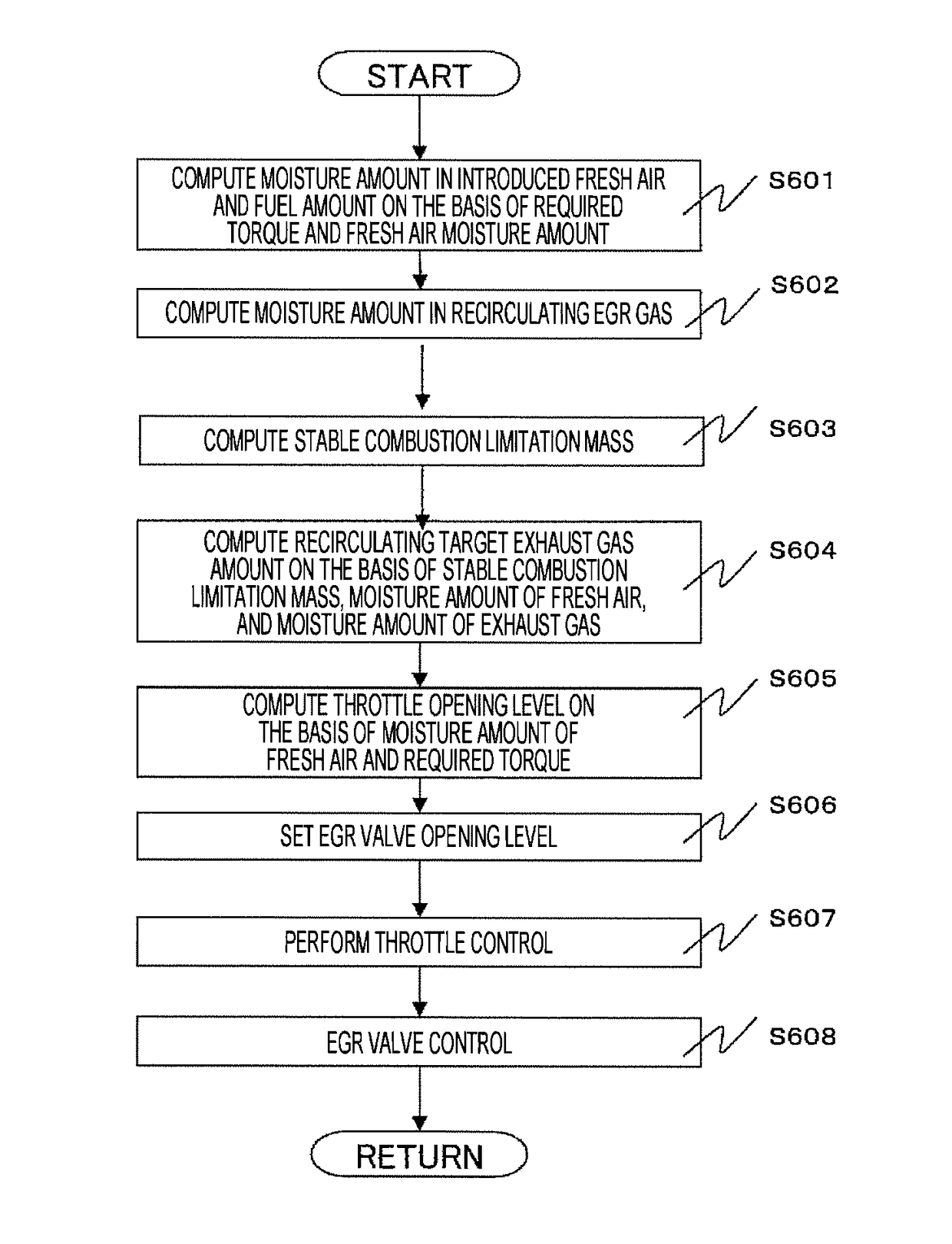
[0041]Example 1 will now be described. FIG. 5 is a schematic system diagram illustrating an automobile in-cylinder injection type gasoline engine provided with a low-pressure EGR flow passage.

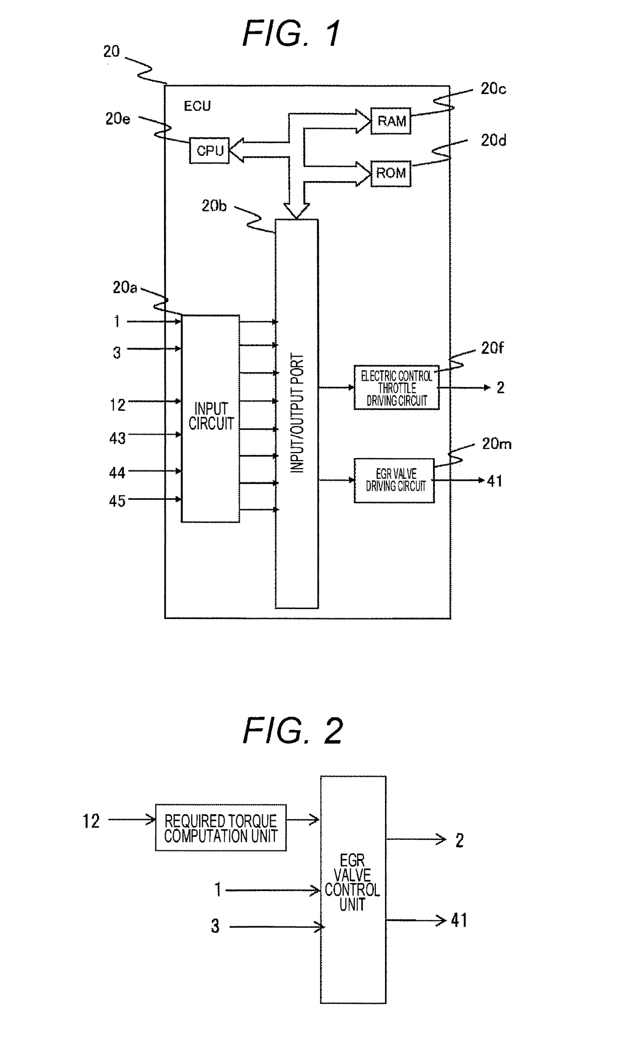
[0042]The engine 100 is an automobile gasoline engine that performs spark ignition type combustion. An air flow sensor 1 that measures an intake air amount, a humidity sensor 3 that detects an intake humidity, a supercharger compressor 4a for supercharging the intake air, an intercooler 7 for cooling the intake air, and an electronic control throttle 2 that adjusts the intake pipe pressure are provided in respective suitable positions of the intake pipe. Here, the humidity sensor 3 is a sensor capable of detecting a relative humidity and an absolute humidity. In addition, each cylinder of the engine 100 is provided with a fuel injection device (hereinafter, referred to as an “injector”) 13 that injects fuel to the inside of the cylinder 14 and an ignition plug 16 that supplies ignition energy. ...

example 2

[0083]Next, Example 2 will be described. FIG. 5 illustrates the engine configuration, and FIG. 2 illustrates the ECU configuration. FIG. 10 illustrates a computation process performed by the EGR valve control unit of FIG. 2. Example 2 is similar to Example 1 except for the process of step S1004. When the target exhaust gas amount is set in step S1004, the catalyst temperature is estimated depending on an increase of the coolant temperature measured using the coolant temperature sensor or the time from the engine start. In addition, the target exhaust gas amount is set depending on the estimated catalyst activation state. In the low-pressure EGR system, the exhaust gas prior to activation of the catalyst contains a lot of active chemical species contributing to the combustion stability, such as carbon monoxide (CO) or nitrogen monoxide (NO), compared to the catalyst warm-up steady state. In the steady state posterior to the warm-up, such active chemical species are converted into sta...

example 3

[0086]Next, Example 3 will be described. With regard to Example 3, FIG. 12 illustrates a configuration of the engine, and FIG. 13 illustrates a computation process performed by the EGR valve control unit of FIG. 2. The configuration of the engine of FIG. 12 is similar to that of FIG. 5 except for the exhaust gas recirculation mechanism. In the configuration of FIG. 12, the exhaust gas is extracted from the upstream side of the turbine of the turbocharger and is recirculated to the downstream side of the compressor. The computation process of FIG. 13 is similar to that of Example 1 of FIG. 6 except for step S1304. In step S1304, when the target exhaust gas amount is set, the coolant temperature measured using the coolant temperature sensor or the target exhaust gas amount depending on the detected EGR gas temperature are set. While the coolant temperature is low, the EGR gas temperature is lowered. If the temperature decreases, unstable combustion easily occurs. Therefore, compared t...


PUM


Abstract

The objective of the present invention is to provide a control device for an internal combustion engine that is able to provide a more stable combustion state by suitably setting the amount of recirculated exhaust gas. The present invention is an internal combustion engine control device equipped with air cylinders and an EGR mechanism that returns exhaust gas emitted from the air cylinders to the intake side of the air cylinders, and is characterized by being equipped with an EGR control unit that controls the EGR flow volume of the EGR mechanism, and a humidity detection means that directly or indirectly detects the humidity of outside air supplied to the air cylinders, with the EGR control unit calculating the moisture amount in the outside air and the moisture amount in the recirculated exhaust gas, and controlling the EGR mechanism on the basis of: a stable combustion limit air cylinder mass, which is set in accordance with the combustion state in the air cylinders; the mass of the air introduced into the air cylinders; the mass of the fuel; and the moisture amounts.

Description

TECHNICAL FIELD[0001]The present invention relates to an engine control device.BACKGROUND ART[0002]Engines incorporating a mechanism for recirculating an exhaust gas in an intake side to reduce fuel consumption of automobiles (EGR: Exhaust Gas Recirculation) have been introduced in the market. The aim of recirculating the exhaust gas is to reduce any power that the piston works (pumping loss) by reducing a manifold vacuum pressure (the difference between a cylinder internal pressure during an intake stroke and the ambient pressure) under the condition that the engine output power is small and to reduce the exhaust loss by suppressing abnormal combustion (knocking) under the condition that the engine output power is relatively large.[0003]In order to remove a pumping loss under the condition that the engine output power is small, it is desired to recirculate the exhaust gas until the intake pipe pressure reaches the ambient pressure. However, since the exhaust gas basically serves as...

Claims


Application Information

Patent Timeline
IPC IPC(8): F02D41/02F02D21/08
CPCF02D41/025F02D43/00F02D21/08F02D45/00F02D41/064F02D41/005F02D2200/0418F02M26/05F02M26/28F02M2026/003Y02T10/40
Inventor ORYOJI, KAZUHIROAKAGI, YOSHIHIKO
Owner HITACHI ASTEMO LTD
Why Eureka
Try Eureka