
Energy conversion systems with power control

a technology of power control and energy conversion system, which is applied in the direction of electric variable regulation, process and machine control, instruments, etc., can solve the problems of inability to meet the needs of large-scale adoption of back-up power systems, high cost, and bulky energy storage devices of power converters

Active Publication Date: 2014-08-05
ENPHASE ENERGY
View PDF50 Cites 62 Cited by
  • Summary
  • Abstract
  • Description
  • Claims
  • Application Information

AI Technical Summary

Benefits of technology

The patent text describes a power conversion system for transferring power from a DC source to an AC grid, which is commonly used in power converters. However, conventional systems have limitations such as high cost, unreliability, and inefficiency. The technical effects of this patent include providing a system that can effectively store and utilize excess energy from the DC source, as well as providing a constant power control method for the power converter to improve its performance and reliability. The patent also includes various embodiments of the power conversion system and its components, such as power conversion devices, PV panels, and a main power path. Overall, the patent aims to overcome the barriers to large-scale adoption of alternative energy sources and provide a more reliable and efficient solution for power conversion.

Problems solved by technology

Energy storage devices for power converters tend to be expensive, bulky, unreliable, and inefficient.
These factors have been barriers to large-scale adoption of alternative energy sources such as solar and fuel cells which generate electricity in the form of DC power.
They have also been barriers to large scale adoption of back-up power systems for computers, residences, schools, businesses, etc.

Method used


Image

  • Energy conversion systems with power control
  • Energy conversion systems with power control
  • Energy conversion systems with power control

Examples


Embodiment Construction

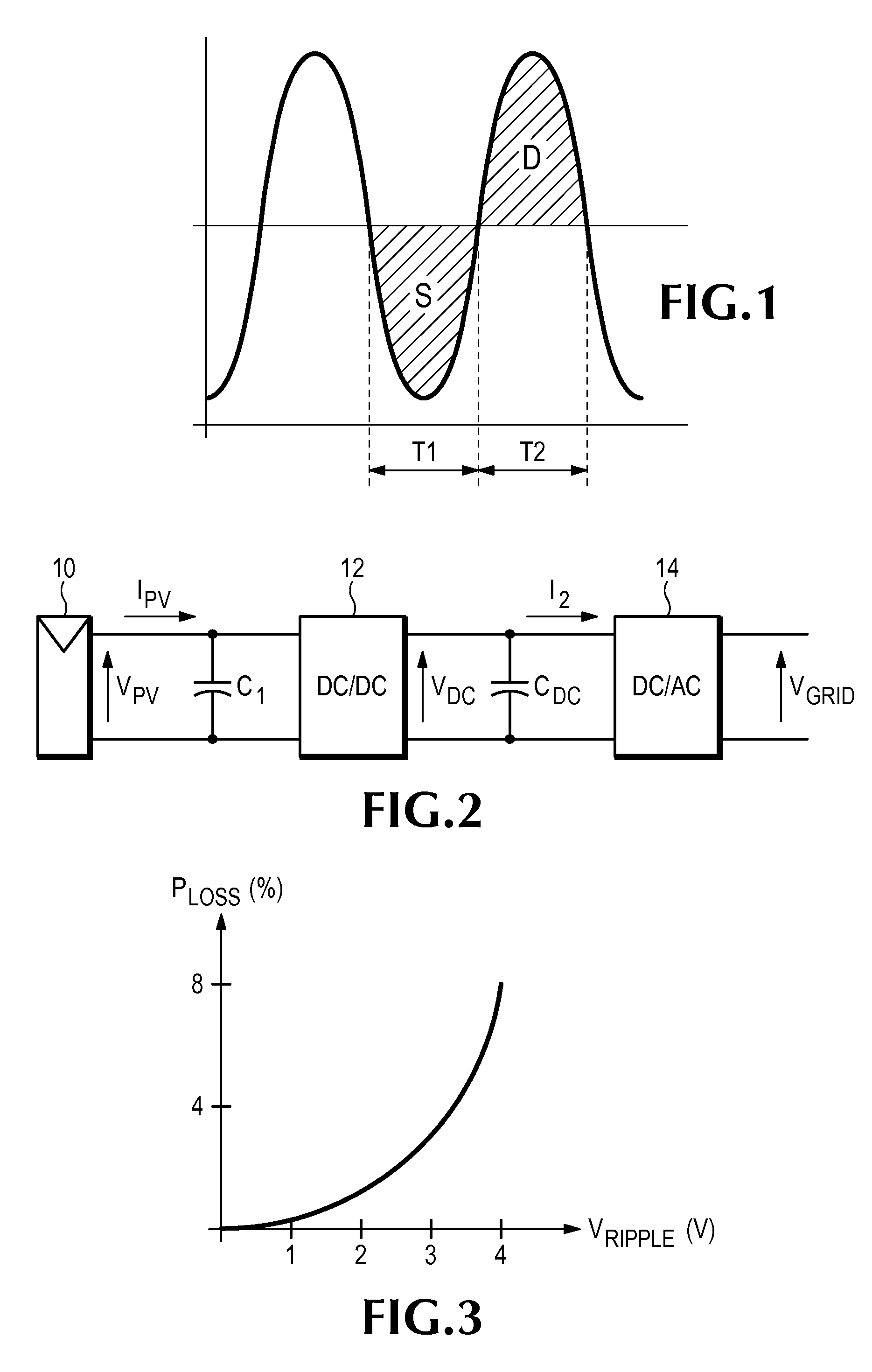
[0042]FIG. 2 illustrates a conventional system for converting DC power from a photovoltaic (PV) panel to AC power. The PV panel 10 generates a DC output current IPV at a typical voltage VPV of about 20 volts, but panels having other output voltages may be used. A DC / DC converter 12 boosts VPV to a link voltage VDC of a few hundred volts. A DC / AC inverter 14 converts the DC link voltage to an AC output voltage VGRID. In this example, the output is assumed to be 120 VAC at 60 Hz to facilitate connection to a local power grid, but other voltages and frequencies may be used.

[0043]The system of FIG. 2 also includes a DC link capacitor CDC and a decoupling capacitor C1. Either or both of these capacitors may perform an energy storage function to balance the nominally steady power flow from the PV panel with the fluctuating power requirements of the grid. Power pulses within the system originate at the DC / AC inverter 14, which must necessarily transfer power to the grid in 120 Hz pulses. I...


PUM


Abstract

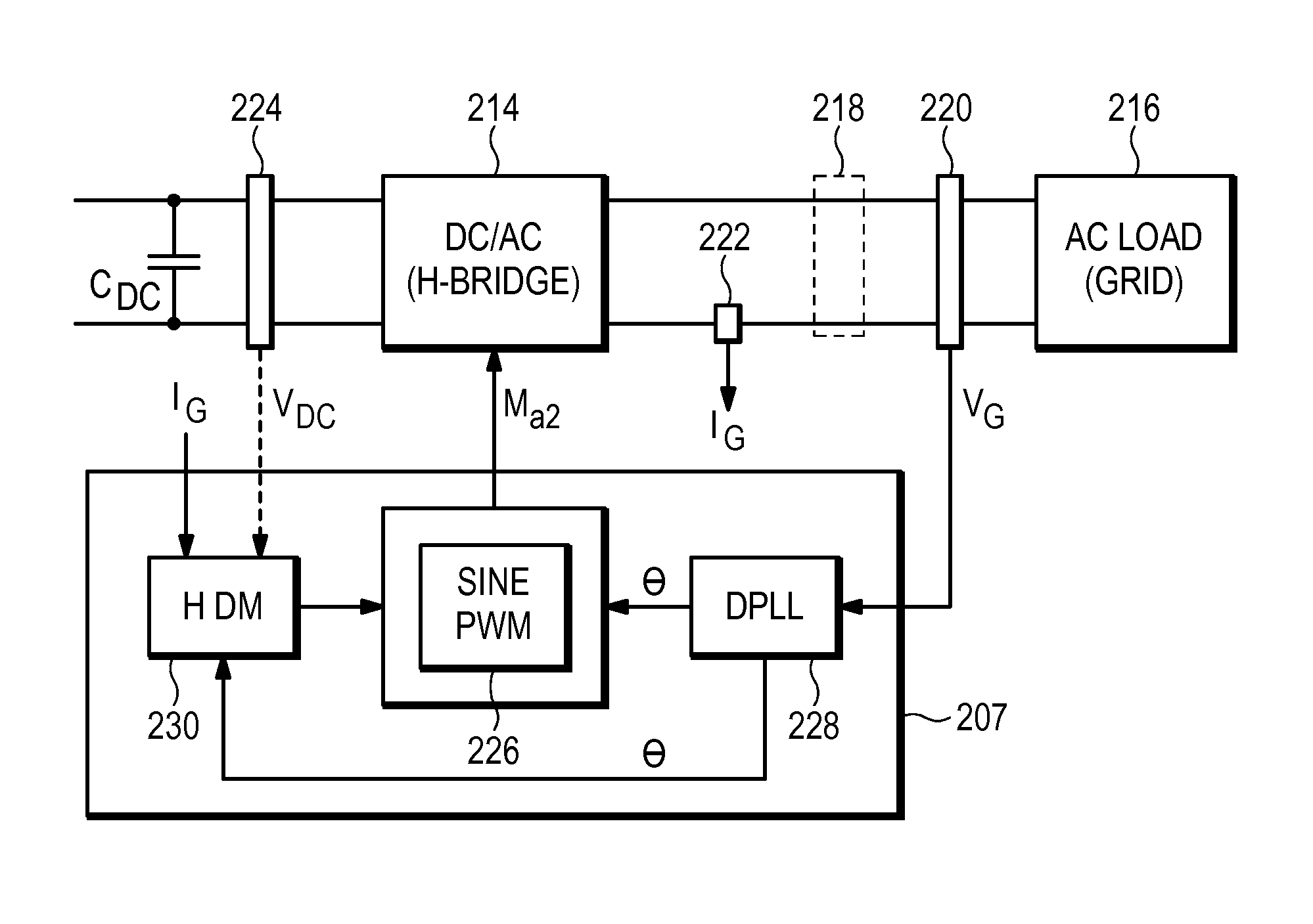
In one embodiment, a power conversion system includes a controller to provide power control to a converter, and a distortion mitigation circuit. In another embodiment, a system includes a converter to transfer power between a power source and a load having fluctuating power demand, and a controller to provide power control, where the controller may selectively disable the power control. In another embodiment, a power conversion system includes a controller to generate a drive signal to provide power control to a power path in response to a sense signal from the power path, where the sense signal is taken from other than the input of the power path, or the drive signal is applied to the power path at other than a first power stage.

Description

CROSS-REFERENCE TO RELATED APPLICATIONS[0001]This application is a continuation-in-part of U.S. patent application Ser. No. 12 / 340,715 filed Dec. 20, 2008, which is incorporated by reference. This application claims priority from U.S. Provisional Patent application Ser. No. 61 / 149,305 filed Feb. 2, 2009, which is incorporated by reference.BACKGROUND[0002]Power converters are used to convert electric power from one form to another, for example, to convert direct current (DC) power to alternating current (AC) power. One important application for power converters is in transferring power from energy sources such as solar panels, batteries, fuel cells, etc., to electric power distribution systems such as local and regional power grids. Most power grids operate on AC current at a line (or mains) frequency of 50 or 60 cycles per second (Hertz or Hz). Power in an AC grid flows in a pulsating manner with power peaks occurring at twice the line frequency, i.e., 100 Hz or 120 Hz. In contrast,...

Claims


Application Information

Patent Timeline
IPC IPC(8): H02M7/537
CPCH02J3/385H02J3/381H02J3/386H02J3/387H02M7/4807Y02E10/58Y02E10/763H02M3/33546H02J2300/30H02J2300/28H02J2300/26Y02E10/56Y02E10/76H02J3/44
Inventor NAIKNAWARE, RAVINDRANATHDITOMMASO, VINCENZOLE, TRIET TUBATTEN, ROBERT D.FIEZ, TERRI SHREEVE
Owner ENPHASE ENERGY
Learn More