Passive cooling and EMI shielding system

a passive cooling and shielding technology, applied in the direction of conduction heat transfer modifications, electrical apparatus casings/cabinets/drawers, instruments, etc., can solve the problems of fan noise, potential equipment downtime, etc., and achieve the effect of reducing the emi radiated and conducting and radiated emi emissions

Active Publication Date: 2014-08-19
CAREFUSION 303 INC
View PDF17 Cites 12 Cited by
  • Summary
  • Abstract
  • Description
  • Claims
  • Application Information

AI Technical Summary

Benefits of technology

[0007]The disclosed system provides passive cooling of electronics and EMI shielding of the same electronics. In the system, a heat sink is located at one edge of the electronics and designed to form a portion of the EMI shielding, with the shielding configured to form a chimney around the heat sink whereby air that has been warmed by the heat sink rises through the chimney and pulls cool air through the heat sink into the chimney. The result is a cooling and shielding system that cools electronics without the use of fans, thereby reducing the noise, cost, and reliability issues associated with cooling fans, while maintaining EMI shielding around the electronics.
[0010]A method of passively cooling electronics while reducing conducted and radiated EMI emissions from the electronics is disclosed. The method includes the step of attaching a heat sink with a base portion to an electronics assembly having at least one electronic component that requires cooling and an interface connector having at least one contact with an interface impedance, the interface connector configured to mate and match impedances with a docking connector having at least one contact with an interface impedance thereby reducing the EMI radiated from conductors connected to the contacts of the docking connector, such that the base portion is thermally coupled to the at least one electronic component. The method includes the step of attaching a conductive enclosure to the electronics assembly so as to form an enclosed volume around the electronics assembly with a first opening fitted around the heat sink and at least one second opening, wherein all non-conductive passages from the enclosed volume to the external environment have at least one cross-sectional opening with a continuous conductive perimeter with a maximum linear length within the opening of less than one quarter wavelength of a determined maximum shielding frequency thereby reducing the EMI radiated through non-conductive passages in the conductive enclosure.

Problems solved by technology

However, placing the processor and motherboard inside a sealed conductive shell has the effect of limiting the amount of cooling air that can enter and leave the enclosure, and therefore a fan is often used to force air through the enclosure to cool the internal electronics, as the processor will overheat without sufficient cooling and shut itself down to avoid permanent damage.
These fans are typically considered to be noisy.
Also, since the functioning of the fan is critical to the operation of the processor and therefore the ADM, the fan is a potential source of downtime of the equipment.

Method used


Image

  • Passive cooling and EMI shielding system
  • Passive cooling and EMI shielding system
  • Passive cooling and EMI shielding system

Examples


Embodiment Construction

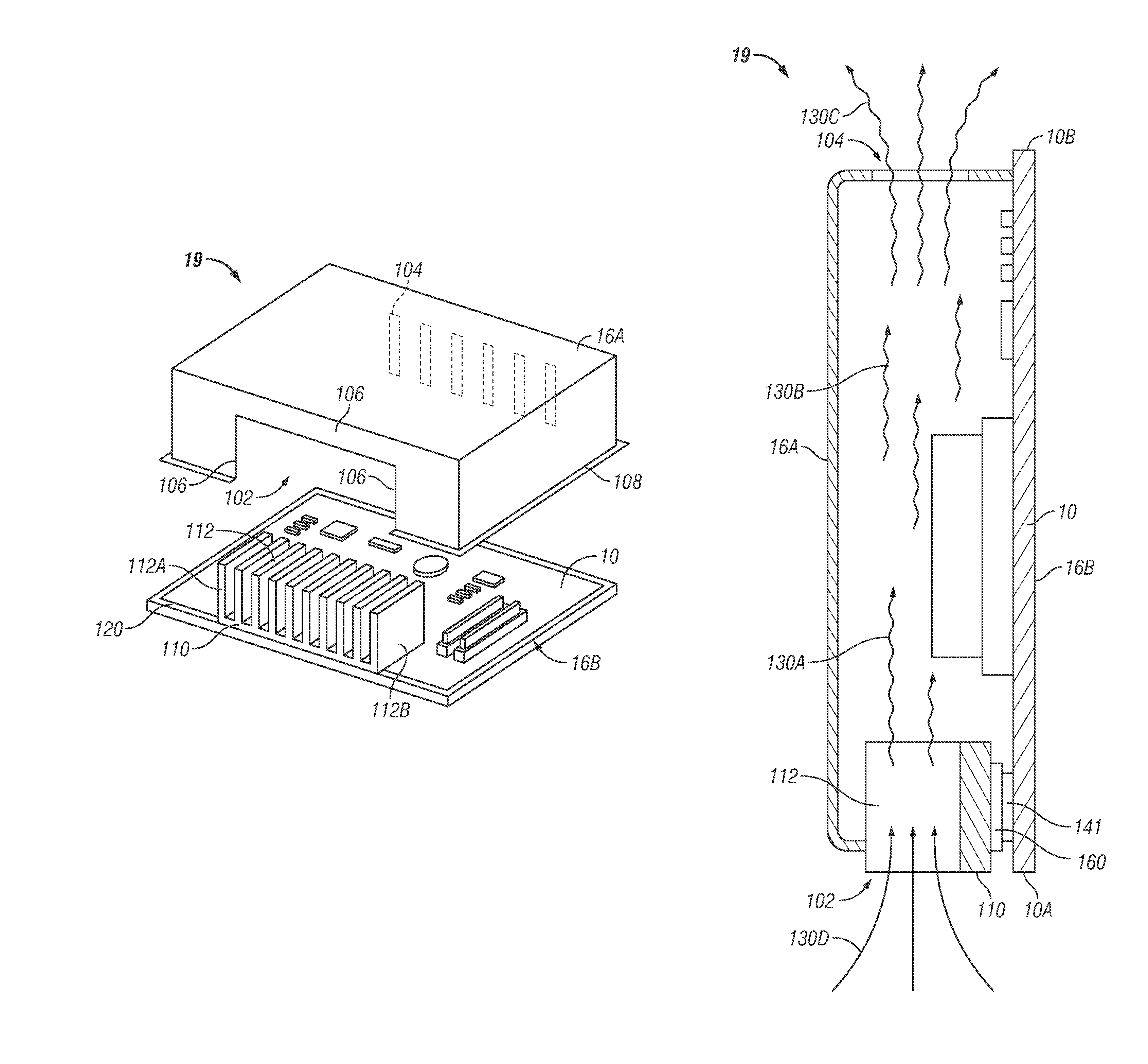
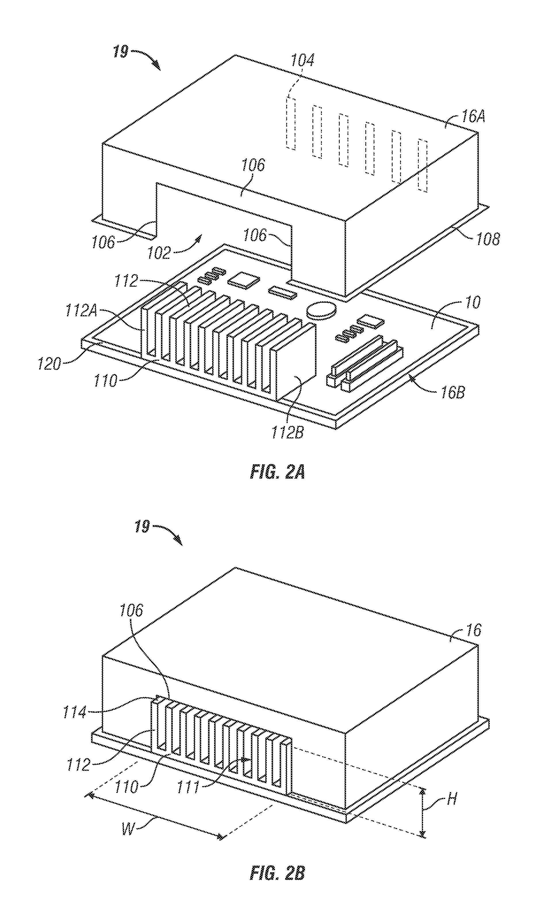
[0021]The following description discloses embodiments of an electronics enclosure that provides for passive cooling of the enclosed electronics while providing EMI shielding of the electronics to meet regulatory requirements on electromagnetic emissions. In certain embodiments, a finned heat sink is thermally coupled to the electronic components to be cooled on an electronics assembly. A conductive enclosure fits around the electronics with an opening fitted around the heat sink and a second opening preferably on the opposite side of the enclosure. The fins are configured such that the gap between the fins is large enough to allow sufficient air flow to provide passive cooling while substantially blocking electromagnetic waves up to a maximum shielding frequency. This avoids the need to have a perforated portion of the conductive enclosure covering the fins and in the air path, which would add flow resistance and decrease the cooling performance.

[0022]In the following detailed descr...


PUM

PropertyMeasurementUnit
shielding frequencyaaaaaaaaaa
frequencyaaaaaaaaaa
frequencyaaaaaaaaaa

Abstract

An electronics enclosure is disclosed that provides passive cooling of electronic components while reducing electromagnetic interference (EMI) emissions. The electronics enclosure includes an electronics assembly with at least one electronic component and a heat sink coupled to the electronics assembly. The heat sink has a base portion configured to thermally couple to the at least one electronic component when the heat sink is coupled to the electronic assembly. The electronics enclosure also includes a conductive enclosure forming an enclosed volume around the electronics assembly. The enclosure has a first opening configured to fit around the heat sink and at least one second opening. All non-conductive passages from the volume to the external environment have at least one cross-sectional opening having a continuous conductive perimeter with a maximum linear length within the opening of less than one quarter wavelength of a determined maximum shielding frequency.

Description

BACKGROUND[0001]1. Field[0002]The present disclosure generally relates to systems and methods of cooling electrical components and, in particular, allowing passive cooling while also providing ElectroMagnetic Interference (EMI) shielding.[0003]2. Description of the Related Art[0004]Hospitals have a need to provide secure storage for certain medications, such as narcotics and controlled substances, while still making the medications available to care givers. One method of providing this secure storage is the use of Automatic Dispensing Machines (ADMs), which typically contain a microprocessor that is functionally connected to the hospital data systems and secure drawers and compartments containing the medications. The software of each ADM is normally configured to allow access to the medications only after certain requirements are met, such as verification that the individual requesting the medication is authorized to do so. The ADMs should be continuously operational as hospitals mu...

Claims


Application Information

Patent Timeline
Patent Type & Authority Patents(United States)
IPC IPC(8): H05K9/00H05K7/20
CPCH05K7/20127G06F1/20Y10T29/49117G06F1/182H04B1/00H05K9/0041H05K7/20336H05K7/2039G16H20/13G16H40/60G16H20/10
Inventor NICOL, DAVID H.JOYCE, MICHAEL DUGANBURGESS, BRENDAN
Owner CAREFUSION 303 INC
Why Eureka
Try Eureka