Phase locked loop circuit having a voltage controlled oscillator with improved bandwidth

a voltage control and phase lock technology, applied in the field of circuits, can solve the problems of ring oscillators suffering from several limitations in high frequency applications, injection locking problems of oscillators, poor jitter performance of pll output,

Active Publication Date: 2014-08-26
NXP USA INC
View PDF18 Cites 5 Cited by
  • Summary
  • Abstract
  • Description
  • Claims
  • Application Information

AI Technical Summary

Problems solved by technology

However, an integrated circuit having multiple PLL circuits with LC oscillators may experience injection locking problems when mutual coupling occurs between the PLL circuits.
The injection locking problems can result in poor jitter performance at the PLL output.
However, ring oscillators may suffer from several limitations in high frequency applications, such as for example, microwave frequencies.
In addition, the tuning circuits may cause extra parasitic loading that limits the maximum frequency.
Further, the VCO conversion gain must be optimized with respect to the VCO frequency tuning range, adding complexity to the PLL design.

Method used


Image

  • Phase locked loop circuit having a voltage controlled oscillator with improved bandwidth
  • Phase locked loop circuit having a voltage controlled oscillator with improved bandwidth
  • Phase locked loop circuit having a voltage controlled oscillator with improved bandwidth

Examples


Embodiment Construction

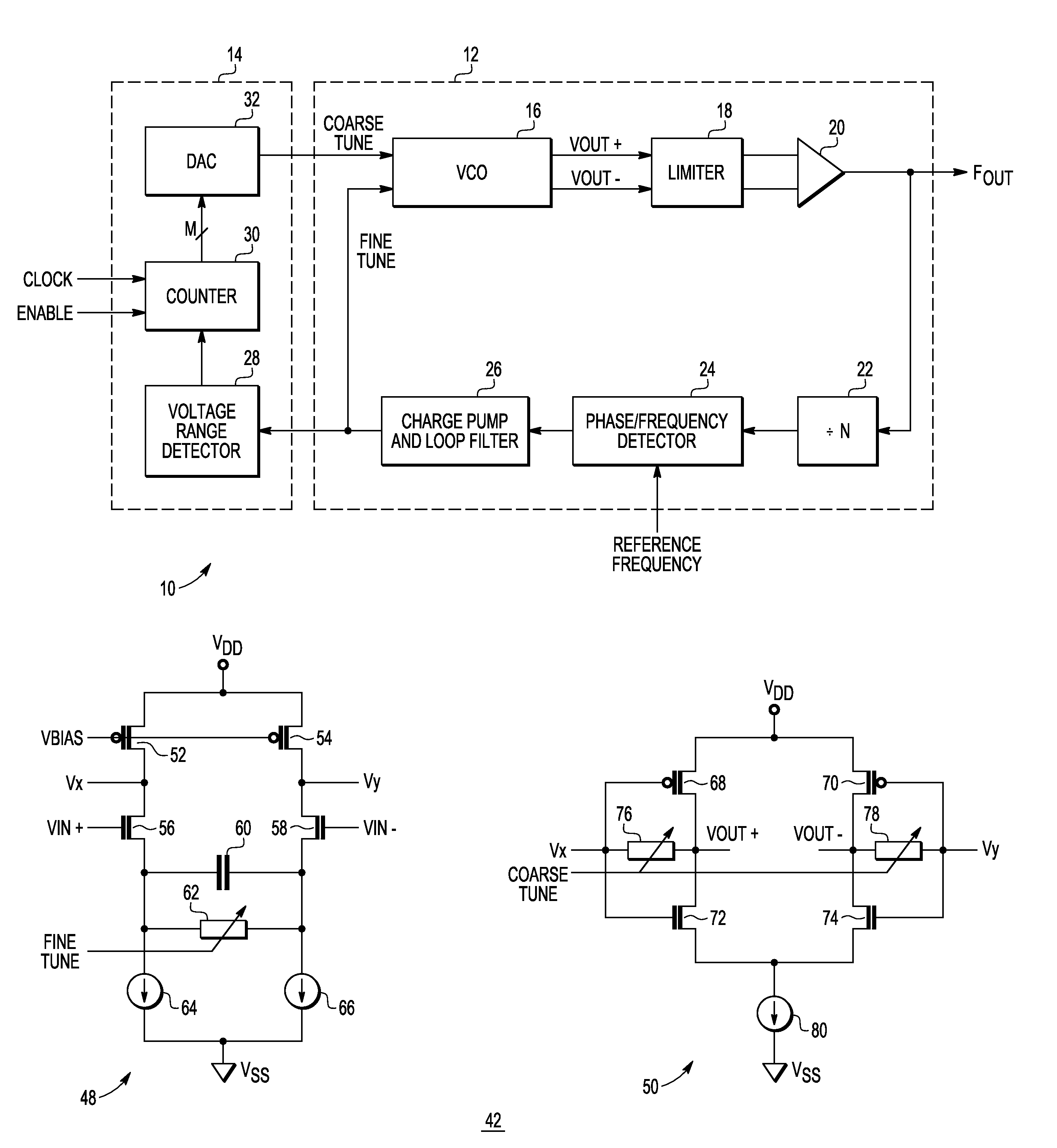
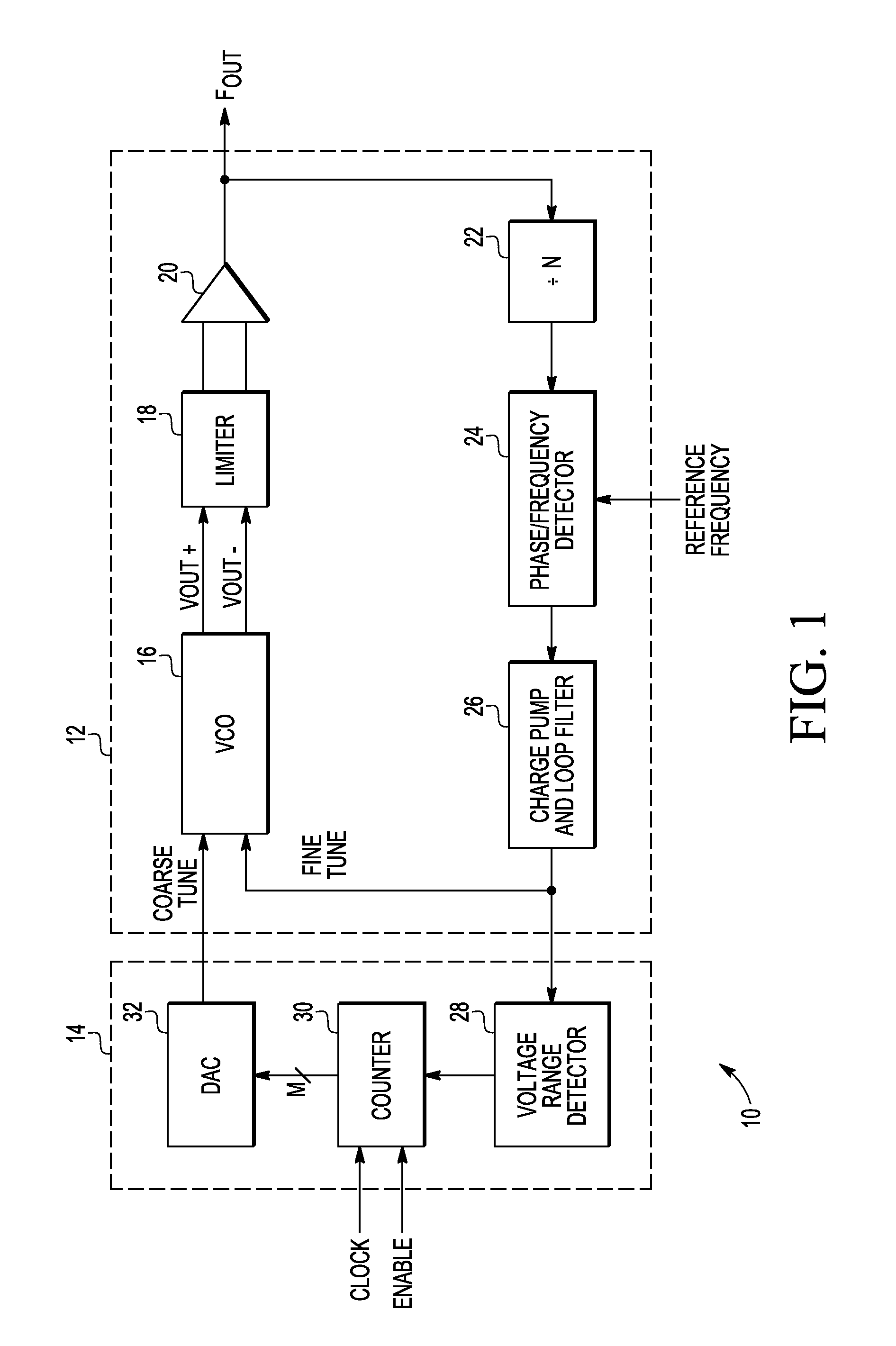
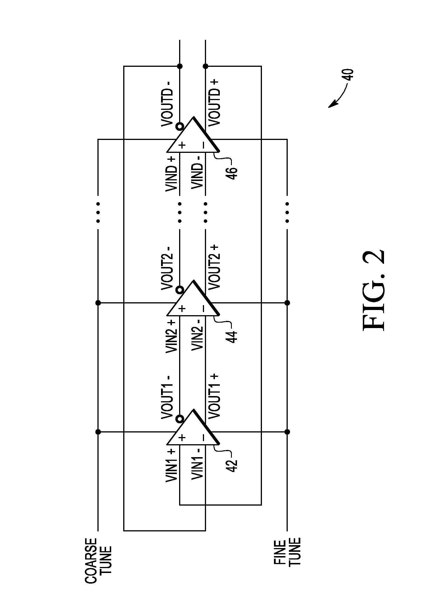
[0016]Generally, there is provided, a PLL system having a ring oscillator based VCO. The ring oscillator has a plurality of composite stages. Each of the plurality of composite stages has a transconductance stage for providing a current mode signal and a transimpedance stage for providing a voltage mode signal. An output of the transconductance stage is coupled to an input of the transimpedance stage. The transconductance stages may include a variable resistance for fine tuning control. A fine tune control voltage is provided to the variable resistance to provide the fine frequency adjustment of the ring oscillator. Each of the transimpedance stages includes a variable resistance. A coarse tune control voltage is provided to the variable resistance of the transimpedance stages to provide a coarse frequency adjustment to the ring oscillator. The variable resistance of the transimpedance stage allows the input of the transimpedance stage to have a relatively low impedance. The transco...


PUM


Abstract

A voltage controlled oscillator includes a plurality of serially connected composite gain stages. A composite gain stage includes a transconductance stage and a transimpedance stage. The transconductance stage has first and second current paths from a first power supply voltage terminal to a second power supply voltage terminal. A first variable resistance is coupled between the first and second current paths. The transimpedance stage has a first inverter and a second inverter. The first inverter has an input terminal coupled to the output of the first current path and an output terminal. The second inverter has an input terminal coupled to the output of the second current path, and an output terminal. A second variable resistance is coupled between the input terminal and the output terminal of the first inverter, and a third variable resistance is coupled between the input terminal and the output terminal of the second inverter.

Description

BACKGROUND[0001]1. Field[0002]This disclosure relates generally to circuits, and more specifically, to a phase locked loop circuit having a voltage controlled oscillator with improved bandwidth.[0003]2. Related Art[0004]A phase locked loop (PLL) circuit is used to generate a clock signal. The PLL circuit generally includes a voltage controlled oscillator (VCO) to generate the clock signal in response to a control voltage. LC (inductor-capacitor) oscillators are used in some VCO circuits to provide high quality clock sources. However, an integrated circuit having multiple PLL circuits with LC oscillators may experience injection locking problems when mutual coupling occurs between the PLL circuits. The injection locking problems can result in poor jitter performance at the PLL output.[0005]To overcome the injection locking problem, a combination of LC oscillators and ring oscillators may be used to prevent two neighboring LC oscillators from running in the same frequency range. Ring ...

Claims


Application Information

Patent Timeline
Patent Type & Authority Patents(United States)
IPC IPC(8): H03K3/03H03L7/00H03B5/02
CPCH03B5/02H03K3/0322H03L2207/06H03L7/00H03L7/0995
Inventor CHANG, YI, CHENG
Owner NXP USA INC
Why Eureka
Try Eureka