

Manufacturing method of a permanent magnet dispoded in a rotating electrical machine
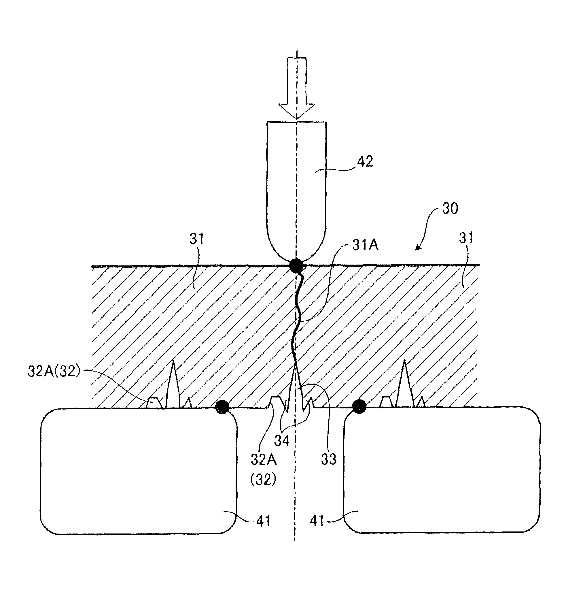
a permanent magnet and rotating electrical machine technology, which is applied in the direction of magnetic circuit rotating parts, magnetic circuit shape/form/construction, magnetic bodies, etc., can solve the problems of heat resistance performance degradation of permanent magnets, misalignment between fractured surfaces, and lower output performance of motors, so as to improve the flatness of cleft surfaces and lower motor output performance.
- Summary
- Abstract
- Description
- Claims
- Application Information
AI Technical Summary
Benefits of technology
Problems solved by technology
Method used
Image

Examples
Embodiment Construction
[0020]A permanent magnet disposed in a rotor core of a rotating electrical machine and a manufacturing method of the same of the present invention will be described below on the basis of an embodiment illustrated in FIGS. 1 to 10.
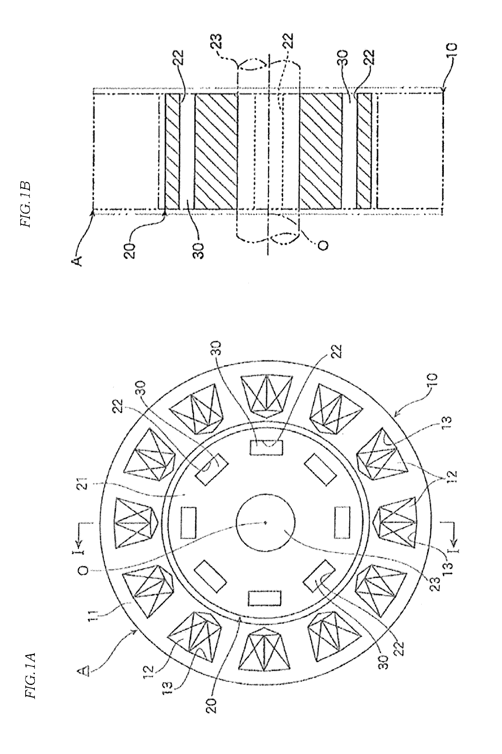
[0021]In FIG. 1, a permanent-magnet embedded rotating electrical machine A (hereinafter referred to simply as a “rotating electrical machine A”) is formed of an annular stator 10 constituting a part of a casing, not shown, and a columnar rotor 20 arranged coaxially with this stator 10.
[0022]The stator 10 includes a stator core 11 and a plurality of coils 12. In the stator core 11, slots 13 are formed at equiangular intervals on the same circumference having a shaft center O at the center. The plurality of coils 12 are accommodated in the slots 13 formed in the stator core 11.
[0023]The rotor 20 includes a rotor core 21, a rotating shaft 23 integrally rotating with the rotor core 21, and a plurality of permanent magnets 30. In the rotor core 21, slots 22 are ...
PUM
| Property | Measurement | Unit |
|---|---|---|
| heat resistance | aaaaa | aaaaa |
| depth | aaaaa | aaaaa |
| depth | aaaaa | aaaaa |
Abstract
Description
Claims
Application Information