Glass railing anchor system

a technology of glass railings and anchors, applied in the direction of protective buildings/shelters, human health protection, climate sustainability, etc., can solve the problems of not properly shimmed or reinforced, not designed for high-wind hurricane zones (hvhz) or other areas susceptible, etc., to achieve the effect of preventing bending and stress along the center line, preventing bending and stress

Active Publication Date: 2014-09-02
POMA & SONS
View PDF4 Cites 29 Cited by
  • Summary
  • Abstract
  • Description
  • Claims
  • Application Information

AI Technical Summary

Problems solved by technology

There are many disadvantages with conventional glass railing anchor systems, such as surface and flush installation systems.
A primary disadvantage with existing glass railing anchor systems is that they are not designed for high wind hurricane zones (HVHZ) or other areas susceptible to high winds.
This is because they are not properly shimmed or reinforced and are susceptible to bending along the centerline, where half the anchor is in tension and the other half in compression.
This weakness results because the anchors 4 used to secure the base 3 to the concrete substrate are installed along a center line making them subject to bending and stress along the center line.
Known systems are also unable to drain water off balconies and they make direct contact with concrete or are embedded in grout causing corrosion of the base and coating.
In surface or side mounted installations, the base is typically aluminum and in direct contact with concrete causing corrosion of the aluminum and failure of coating.
However, most grouts are highly alkaline causing corrosion of the aluminum and failure of coating.
These known attachment methods also do not provide a permanent waterproof seal of the anchor base or drainage, which permits water intrusion directly into the center of the concrete defeating most waterproofing techniques and promoting corrosion.
In addition, typical base dimensions provide insufficient use of materials, wherein the base is up to three times heavier than necessary and more difficult to install.
Moreover, conventional U-shaped bases typically have tall profiles and square shoulders giving them an artificial appear

Method used


Image

  • Glass railing anchor system
  • Glass railing anchor system
  • Glass railing anchor system

Examples


Embodiment Construction

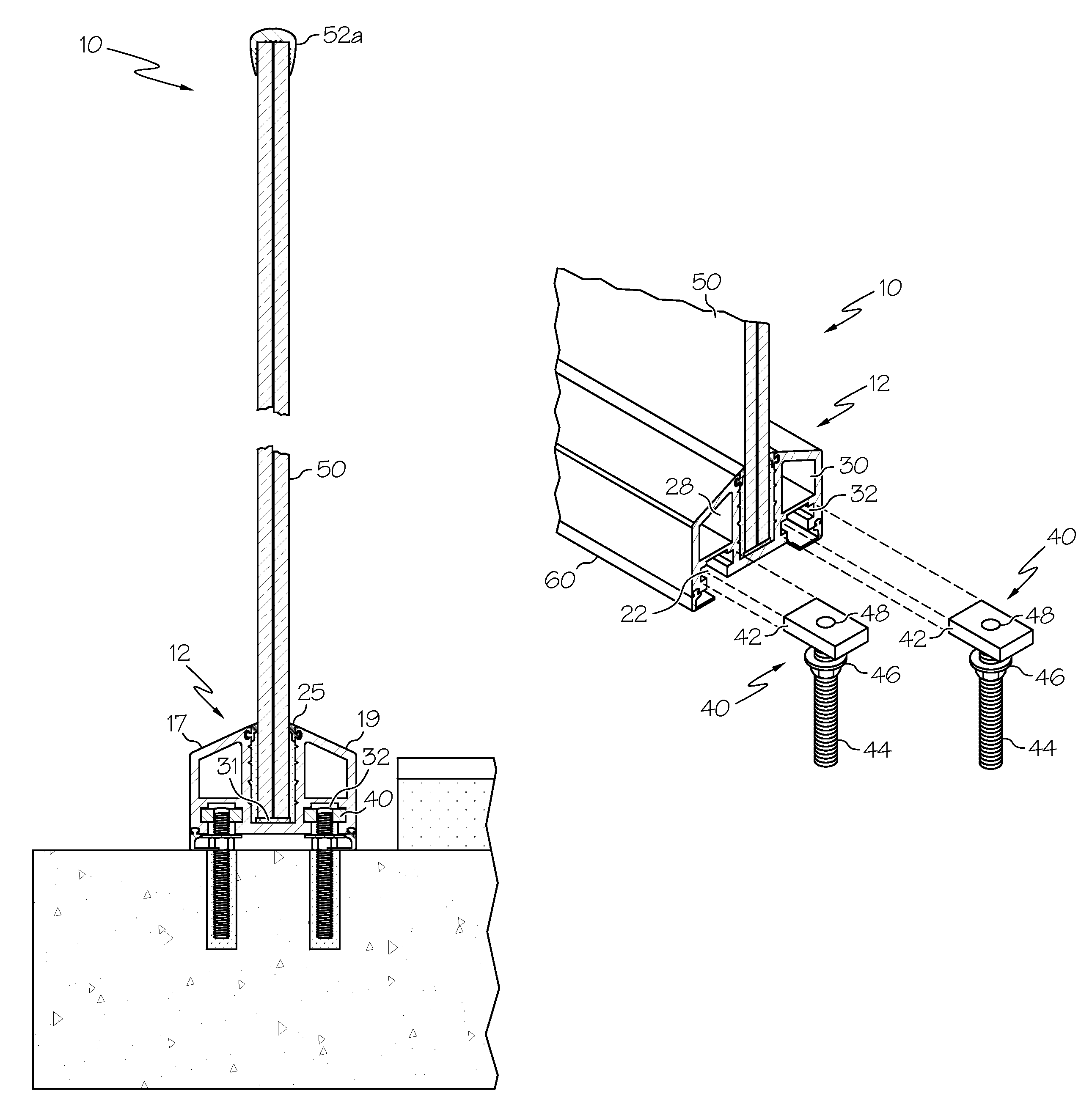
[0023]With reference to the drawings, FIGS. 5-10D depict the preferred and alternative embodiments of the instant invention which is generally referenced as a glass railing anchor system and, or by numeric character 10. The instant invention 10 comprises a glass railing anchor system that is designed to withstand the forces realized in high velocity hurricane zones (“HVHZ”) and comparable high wind zones. The glass railing anchor system 10 is adapted for installation on balconies of high rises, as shown in FIG. 5. The instant invention 10 may also be installed on balconies of buildings in high wind zones, such as on the beach or on decks. Referring to FIG. 5, the glass railing anchor system 10 generally comprises an aluminum base 12 and at least one panel 50 supported by the base 12, and may also include a variety of caps 52. The instant invention 10 is described in more detail herein below.

[0024]With reference to FIGS. 5 to 10D, the glass railing anchor system 10 comprises an elong...


PUM


Abstract

An improved glass railing anchor system for multiple glass panels in high-rise buildings which can experience hurricane strength winds, and which includes an elongated base member having two hollow wall sections which create a channel for receiving the glass panels. Aligned with and beneath the hollow wall sections are integral keyways which receive T-shaped anchors that also elevate the base member to allow for drainage. The anchors are slidable and can be selectively positioned for easy and secure installation. The base member, hollow wall sections, keyway and drainage areas can be integrally incorporated into a unitary device.

Description

CROSS REFERENCE TO RELATED APPLICATIONS[0001]This application claims the benefit of U.S. Provisional Application No. 61 / 602,662 filed on Feb. 24, 2012.STATEMENT REGARDING FEDERALLY SPONSORED RESEARCH OR DEVELOPMENT[0002]N / ACOPYRIGHT NOTICE[0003]A portion of the disclosure of this patent document contains material that is subject to copyright protection. The copyright owner has no objection to the facsimile reproduction by anyone of the patent document or patent disclosure as it appears in the Patent and Trademark Office patent file or records, but otherwise reserves all copyrights rights whatsoever.BACKGROUND OF THE INVENTION[0004]1. Field of the Invention[0005]This invention relates generally to an anchor system for glass railings, and more particularly, to a glass railing anchor system that uses two rows of adjustable anchor bolts along a glass railing anchor that are staggered along a two lines to distribute tensile and compressive loads on the anchor and anchor bolts allowing us...

Claims


Application Information

Patent Timeline
IPC IPC(8): E04H17/16
CPCE04H17/16E04F11/1853E04H9/14E04F11/1812Y02A50/00
Inventor POMA, FRANKPOMA, JASONPOMA, JUSTIN
Owner POMA & SONS
Why Eureka
Try Eureka