
Holder/impactor for contoured bone plate for fracture fixation

a bone plate and contoured technology, applied in bone drill guides, medical science, surgery, etc., can solve the problems of insufficient bone in the end fragment, difficult use of bone plates, and relatively small end fragments, so as to reduce fragments, resist shortening, and prevent loss of length

Active Publication Date: 2014-09-02
TRIMED
View PDF11 Cites 9 Cited by
  • Summary
  • Abstract
  • Description
  • Claims
  • Application Information

AI Technical Summary

Benefits of technology

The patent describes a hook plate that is used to treat fractures of the distal radius. The hook plate is designed to hold the volar or dorsal rim of the distal radius and provide subchondral support to prevent loss of length. The hooks on the plate do not angle back in line with the long axis of the bone, but rather angle along the direction of the subchondral bone. This design helps to resist shortening of the fragment and acts as a buttress for the distal bone fragments. The implant can be applied and hammered into place, eliminating the need for pre-drilled pilot holes. The number and location of the implants can be individualized to the specific pattern of the injury, allowing for customization of fixation.

Problems solved by technology

Difficulties in using bone plates may arise in certain fractures occurring relatively close to the end of a bone, creating a relatively small end fragment.
In this situation, there may simply be not enough bone available in the end fragment to accommodate a sufficient number of screws to achieve secure fixation.
As a result, a surgeon using a conventional bone plate may use a suboptimal number of screws, which can lead to postoperative failure.
In such situations, only a very small distal fragment may be present, providing inadequate room for more than one or two screws to be placed.
Moreover, since the deep portion of this bone is a part of the overall ankle joint, screws cannot be placed through both cortices, as is commonly practice with plate / screw techniques.
Accordingly, the surgeon may be faced with the undesirable situation of having the patient leave the operating room with only one or two screws engaging a bone surface directly under a bone plate.
However, this terminal bone fragment may still remain far from being well secured.
In addition, this technique does not address the problem of creating holes in the bone at the correct depth for engagement by the hooks, but rather relies on manual pressure on the plate to attempt penetration of the bone by the hooks at whatever level they happen to contact.
As can be noted by the examples in this article, the hooks may fail to penetrate the bone resulting in less than satisfactory engagement and fixation of the terminal fragment by the hooks as well as prominence of the hooks in the soft tissue because of incomplete seating.
Finally, since these implants have hooks that extend an equal distance from the end of the plate, this design does not allow completely seating of both hooks in the common situation in which the bone surface at the terminal end is at an angle to the plane that is perpendicular to the long axis of the bone.
These fractures are often comminuted and unstable.
However, in the case of the distal radius fractures, fixation that would produce this type of compressive loads between the articular fragments and the shaft may result in migration of the fragments, loss of length, malunions and failure.
First, since there are four posts integrally formed with the plate, a somewhat cumbersome drill guide apparatus is required to be applied to the bone in order to drill the holes for all four posts simultaneously.
This can be significantly difficult to achieve.
Since this plate was intended to be a single size approach to variable fracture patterns, fracture elements didn't always line up in the optimal position for insertion of the tines.
In other words, this design lacks the flexibility often required to avoid placing tines directly through fracture lines (which can push fragments apart, contributing to instability).
These issues can lead to inadequate fixation.
However, this design still remains a one size fits all solution, and lacks flexibility to line up fixation for some complex fracture patterns.
Although this approach adds further flexibility to the direction of the fixation pegs, it still requires the surgeon to restore and hold the anatomy while the fixation is taking place, which can sometimes be difficult to perform.
In addition, this design does not solve the problem of avoiding the placement of pegs through fracture lines, since the relative position of the peg holes is fixed, and moving the entry of one peg by shifting the plate to a different location results in corresponding movement of the placement locations of all of the other associated pegs.
Since it is known that thick implants close to the rim of the distal radius may often cause irritation and even rupture of important tendons and other vital structures nearby, existing volar generally plates do not extend to the distal rim.
As a result, small fractures of the distal volar rim are often not be secured by these plate designs, which can result in the fragment flipping over the edge of the plate, potentially causing catastrophic loss of reduction and dislocation of the carpal bones of the wrist.
These multiple steps can be somewhat difficult and time consuming, and may be an objection to application of this technique.
However the surgical technique for this type of implant does require pre-drilling the holes for insertion of the legs of the buttress pin.
These steps can be difficult to perform, often requiring surgeons with above average ability and experience.
In addition, since these types of implants are a type of bent wire, they lack the strength and rigidity of larger plates.
Although early designs such as the LCP Hook Plate manufactured by Synthes, Inc. wrap around the end of the bone, these types of implants do not achieve any internal purchase of the fragment to be secured, and may have very limited to no purchase overall, resulting in poor rotational stability and limited resistance to sideways drift of the terminal fragment.
For fixation of the distal radius, however, the configuration of these types of hook plates is not optimal, especially for fractures involving the volar or dorsal rim.

Method used


Image

  • Holder/impactor for contoured bone plate for fracture fixation
  • Holder/impactor for contoured bone plate for fracture fixation
  • Holder/impactor for contoured bone plate for fracture fixation

Examples


Embodiment Construction

[0103]While several different embodiments of the present invention are described herein and shown in the various figures, common reference numerals in the figures denote similar or analogous elements or structure amongst the various embodiments.

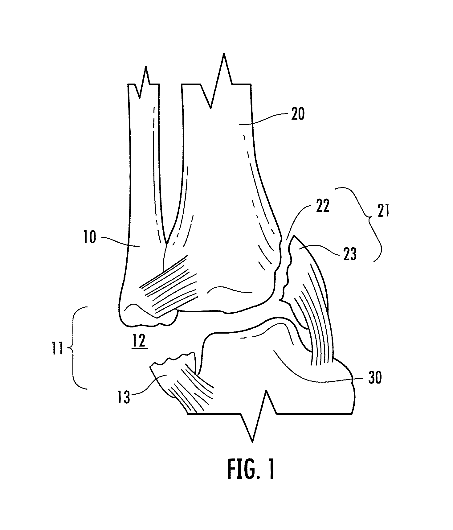
[0104]A simplified anterior view of a portion of the right human ankle is shown in FIG. 1 as comprising fibula 10, tibia 20, and talus 30. Right fibula 10 is shown having a fracture of the lateral malleolus 11 thereof, creating a small terminal fragment 13 proximate fracture site 12. Simultaneously, right tibia 20 is shown having a fracture of the medial malleolus 21 thereof, creating a small terminal fragment 23 proximate fracture site 22.

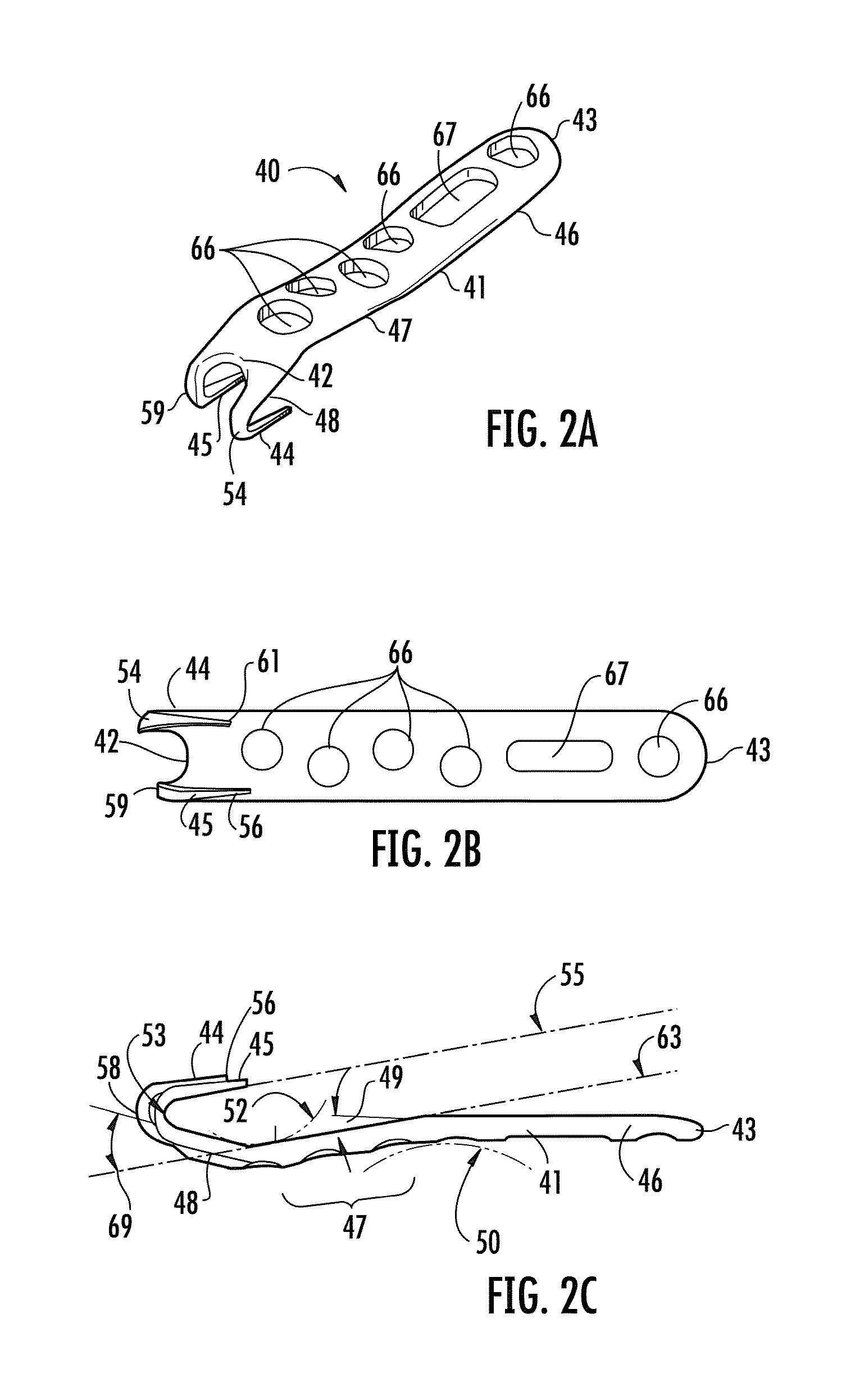
[0105]A six-hole left offset bone plate 40 of the present invention, configured for use in conjunction with fractures of the lateral malleolus, is shown in FIGS. 2A through 2F as comprising an elongated body 41, having a first end 42 proximate first hook member, or tooth member 44 and second hook member, or...


PUM


Abstract

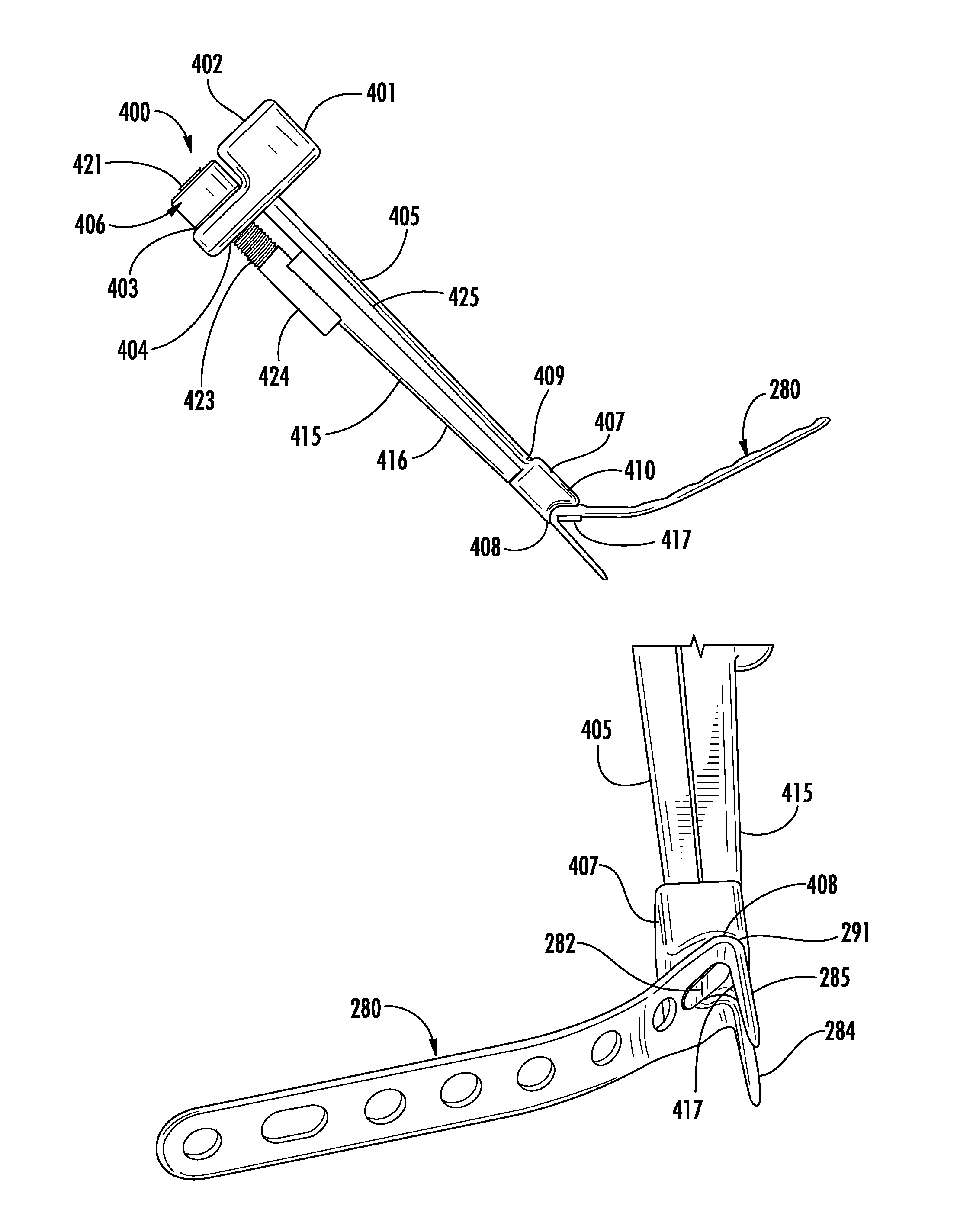
A bone fixation plate for fixation of fractures having a small terminal bone fragment, such as fractures of the distal radius. The plate includes an elongated body, and two hook members extending from a first end of the elongated body. A contoured region is configured to approximate the surface contour of the distal radius proximate the volar rim, the dorsal rim, or the radial arm. Each hook member is configured to provide subchondral support to a distal bone fragment, without causing shortening of the fragment into the metaphyseal bone, and without providing a bending torque directed to the base of the plate. The tooth members of the hook plate are preferably sharpened at their tips and edges to facilitate their impaction. A holder / impactor for gripping the radial hook plate, and for further facilitating impacting of the hook plate without the need to pre-drill pilot holes, is also provided.

Description

CROSS-REFERENCE TO RELATED APPLICATIONS[0001]This application is a continuation-in-part of pending U.S. patent application Ser. No. 13 / 103,658, filed May 9, 2011, the entirety of which is hereby incorporated by reference, which is a division of U.S. patent application Ser. No. 12 / 114,916 filed May 5, 2008, now U.S. Pat. No. 8,177,822, the entirety of which is hereby incorporated by reference.BACKGROUND OF THE INVENTION[0002]1. Field of the Invention[0003]The present invention relates, in general, to the fixation of bone fractures and, more particularly, to the fixation of bone fractures having small fragments proximate a terminal end of a bone.[0004]2. Description of Related Art[0005]Plates and screws are well accepted techniques for fixation of fractures. The standard bone plate is a planar bar of material, usually metal, having circular and / or slotted holes through which bone screws are placed. The bone plate is used to span a fracture and fixation screws are placed through holes ...

Claims


Application Information

Patent Timeline
Patent Type & Authority Patents(United States)
IPC IPC(8): A61B17/58A61B17/17A61B17/80A61B17/92
CPCA61B17/809A61B17/92A61B17/8061A61B17/808A61B2017/922A61B17/1728A61B2017/1775A61B17/1739A61B17/1775
Inventor MEDOFF, ROBERT J.SHIN, ALEXANDER Y.
Owner TRIMED
Learn More