Piezoelectric resonator operating in thickness shear mode

a thin film resonator and shear mode technology, applied in piezoelectric/electrostrictive device details, piezoelectric/electrostrictive/magnetostrictive devices, piezoelectric/electrostriction/magnetostriction machines, etc., can solve the problem of large difficulty in achieving uniform c-axis tilting, sensor is not able to operate in liquid, and needs non-standard deposition tools

Inactive Publication Date: 2014-09-09
SNAPTRACK
View PDF20 Cites 83 Cited by
  • Summary
  • Abstract
  • Description
  • Claims
  • Application Information

AI Technical Summary

Problems solved by technology

However, such sensors are not able to operate in a liquid when using longitudinal waves as for mobile phones.
The main disadvantage of this technique is the need for non-standard deposition tools and large difficulties to achieve uniform c-axis tilting.
The disadvantage is the creation of an S3 component of strain below the electrode fingers, leading to a longitudinal wave component, and thus to emission into the liquid.

Method used


Image

  • Piezoelectric resonator operating in thickness shear mode
  • Piezoelectric resonator operating in thickness shear mode
  • Piezoelectric resonator operating in thickness shear mode

Examples


example 1

High Performances In-Liquid Sensing

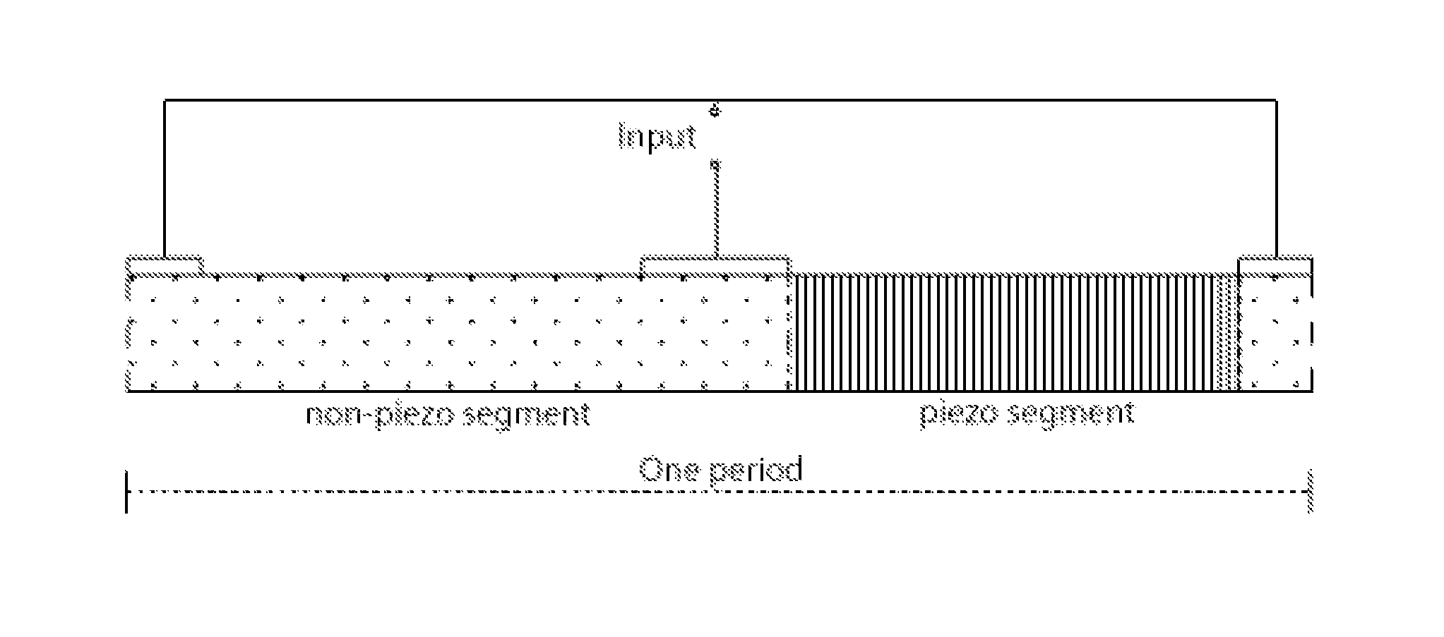
[0047]A principle of in-liquid sensor based on shear mode resonator is shown in FIG. 1. The top surface of the device is functionalized to attract certain types of impurities from liquid. Once the impurities are attached to the surface, acoustic properties of the resonator have been changed and that results in a shift of resonance frequency. By the size of shift, the quantity of attracted substances can be determined and conclusions drawn about the concentration of the impurities in the liquid. By using different chemical tools for functionalization of the surface it is possible to fabricate sensors for different kinds of impurities. Generally speaking, everything that can affect acoustic properties of the resonator may be detected.

[0048]In fact, such sensor is the analog of the well-known quartz crystal microbalance (QCM) device that provides sensing in a similar way. QCM is based on a special cut of mono-crystal of quartz and then is polished to ...

example 2

Piezoelectric Transformer

[0049]Another potential application is a piezoelectric transformer (PT). A potential device, shown in FIG. 10, consists of a primary winding (top layer), matching layer, and secondary windings (bottom layer). The primary winding is a patterned AlN thin film, and the secondary one is a non-patterned, standard piezoelectric AlN film. A floating electrode can be added to the secondary winding. An input AC voltage is applied to primary winding and an output AC voltage is taken from the secondary one. In operation, the primary and secondary windings are acoustically coupled by thickness-shear mode of vibration through matching layers, as shown in FIG. 11. Excitation of shear wave is produced in the primary winding in the same way as in the resonator.

[0050]Nominal value for output / input transformation is equal to the number of periods in a patterned film. For the simulation shown in FIG. 11, it is equal to 2. However, it should be recognized that the transformatio...


PUM


Abstract

An acoustic wave resonator device comprising a resonant layer that comprises a series of side-by-side areas of first and second dielectric materials. In one embodiment the first dielectric material is a piezoelectric, in particular the first dielectric material can be a piezoelectric and the second dielectric material can be non-piezoelectric. In another embodiment, the first dielectric material is a piezoelectric of first polarity and the second dielectric material is a piezoelectric of opposite polarity or different polarity. Where needed, the resonant layer is supported on a reflector composed of series of layers of high acoustic impedance material(s) alternating with layers of low acoustic impedance material(s). For example, the reflector comprises AlN, Al2O3, Ta2O5, HfO2 or W as high impedance material and SiO2 as low impedance material.

Description

[0001]This application is a 371 of international application No. PCT / IB2009 / 053274 filed Jul. 28, 2009, which claims the benefit of U.S. Application Ser. No. 61 / 085,479 filed Aug. 1, 2008 which is incorporated by reference herein in its entirety.FIELD OF THE INVENTION[0002]The present invention relates generally to piezoelectric micro-devices and, in particular, to thin film resonators operating in thickness-shear mode. Potential applications are in sensors, RF oscillators and transformers.BACKGROUND OF THE INVENTION[0003]A list of referenced documents is appended to the end of the Description.[0004]Piezoelectric resonators are electro-mechanical resonators. The resonance is due to shape, density and elastic constants of the mechanically resonating body containing piezoelectric material. The piezoelectric effect permits to couple the mechanical resonance to an electric circuit. The use of piezoelectric thin films allows very large resonance frequencies in the 1-10 GHz range by trapp...

Claims


Application Information

Patent Timeline
Patent Type & Authority Patents(United States)
IPC IPC(8): H03H9/17H03H9/56H01L41/04H03H9/58H01L41/107H03H9/02
CPCH03H9/562H03H9/583H03H9/171H01L41/107H03H9/02015H03H9/175H10N30/40
Inventor MILYUTIN, EVGENYMURALT, PAUL
Owner SNAPTRACK
Why Eureka
Try Eureka