
Piezoelectric sensor based smart-die structure for predicting the onset of failure during die casting operations

a smart-die structure and sensor technology, applied in the direction of force sensors, instruments, force/torque/work measurement apparatus, etc., can solve the problems of long-term detrimental effect on the properties of the die-protecting layer, small technology available to predict structural problems of dies, and poor crystallinity, so as to increase the piezoelectric response of the piezoelectric film, the density of the aln thin film is reduced, and the piezoelectric film is increased.

Inactive Publication Date: 2014-09-16
COLORADO SCHOOL OF MINES
View PDF14 Cites 1 Cited by
  • Summary
  • Abstract
  • Description
  • Claims
  • Application Information

AI Technical Summary

Benefits of technology

Enables early detection of die coating failure, preventing irreversible damage and extending die life by allowing for proactive maintenance, thereby reducing energy consumption and wastage.

Problems solved by technology

Due to the severe mechanical and thermal cyclic loading, die failure is a significant issue in die-casting that results in considerable energy consumption and wastage.
The severe conditions of die casting process still have a long-term detrimental effect on the properties of the die-protecting layer.
The prolonged operation at these conditions can initiate a failure in the die coating, which can rapidly extend to the main die surface, again causing failure.
The important issue, therefore, is to determine the point at which the protective surface coating approaches failure and indicates the need for its change.
Although technological advances have led to an extension of die life, there is still little technology available to predict structural problems with dies.
It is a ‘post mortem’ procedure that does not allow the die caster to become aware of the problem until the problem is irreversible.
The onset of failure in the protective layer (coating system) is always accompanied by a sudden increase in the stress level, which the sensor is operable to detect.
The choice of material is an important issue due to the degradation of piezoelectric properties in most materials subjected to die casting temperatures (>600° C.).
Additionally, use of a TiN thin film barrier layer may increase the piezoelectric response of the film.

Method used


Image

  • Piezoelectric sensor based smart-die structure for predicting the onset of failure during die casting operations
  • Piezoelectric sensor based smart-die structure for predicting the onset of failure during die casting operations

Examples


Embodiment Construction

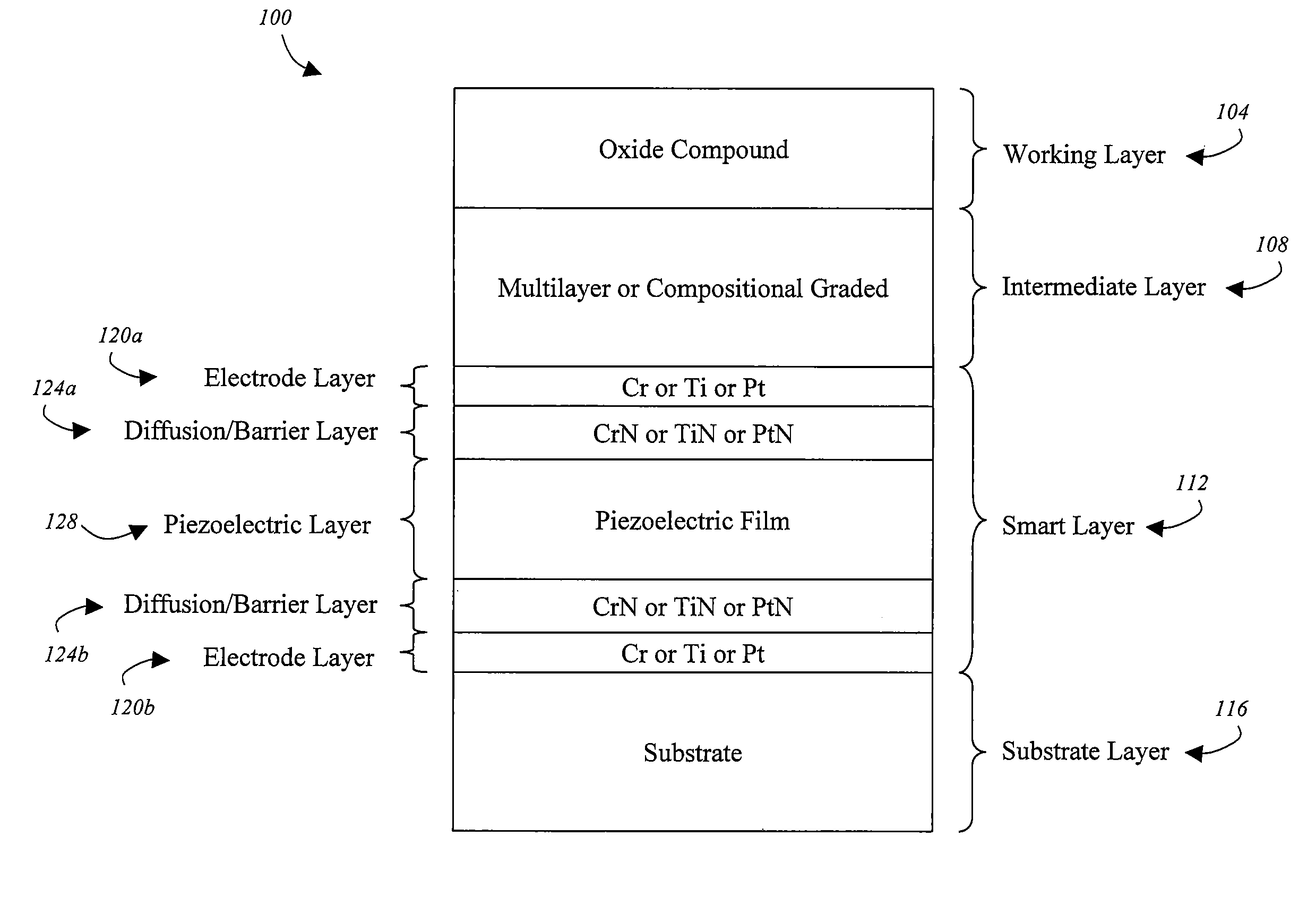
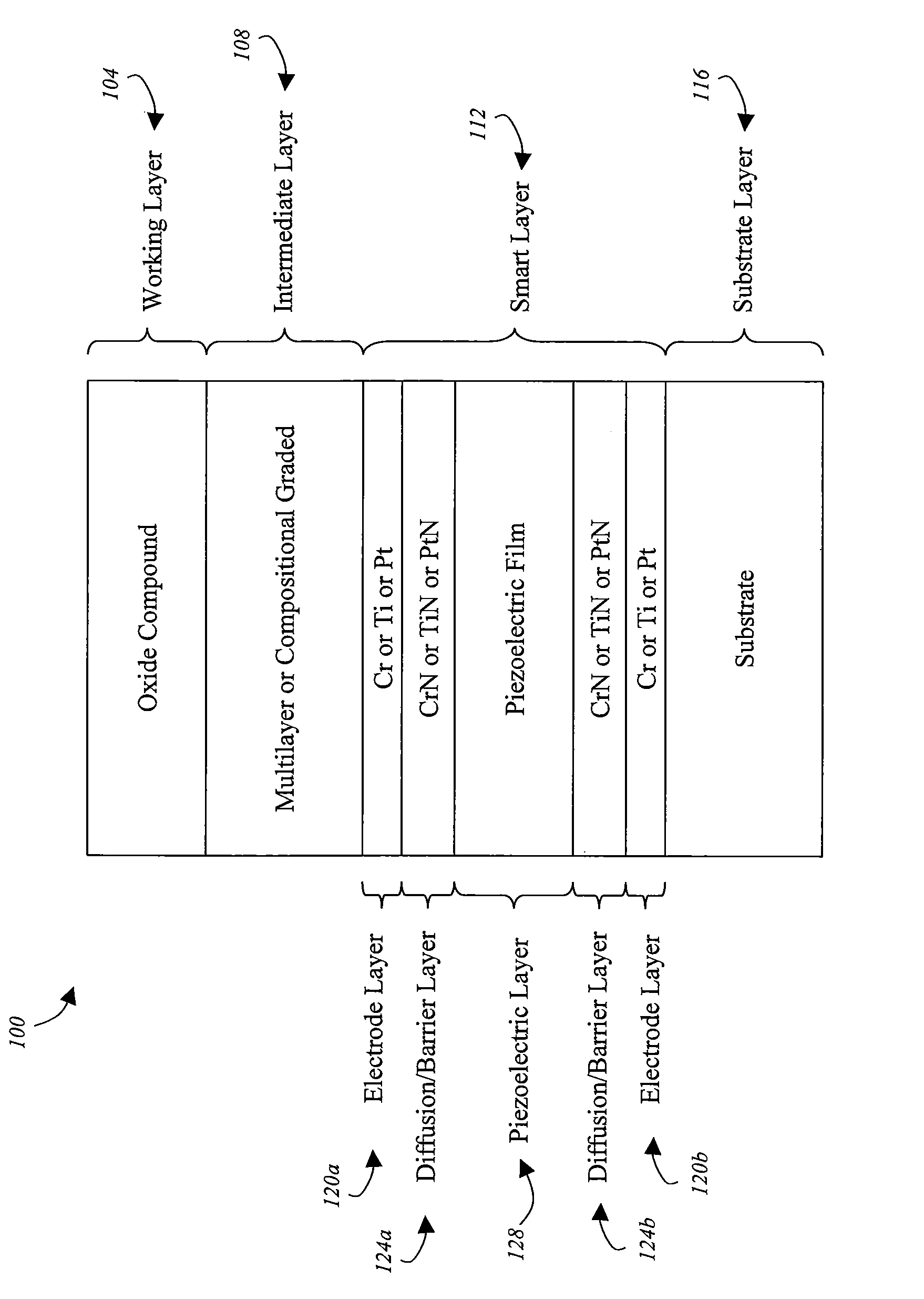
[0031]With reference now to FIG. 1, an exemplary smart die 100 coating architecture will be described in accordance with at least some embodiments of the present invention. The die 100 structure may include a working layer 104, an intermediate layer 108, a smart layer 112, and a substrate layer 116. One or more of the layers may be deposited on the substrate layer 116 via a thin film deposition process as will be discussed in further detail below. The working layer 104 is generally the outermost layer of the die 100. Thus, the working layer 104 is generally the layer of the die 100 that contacts the material that is being die-cast. The working layer 104 should preferably be composed of a material that interfaces well with the material being die-cast. For example, an oxide compound may be used for die-casting operations where aluminium or similar metals are die-cast. A first surface (e.g., the outermost surface) of the working layer 104 may be the side that physically contacts the ma...


PUM

PropertyMeasurementUnit
thicknessaaaaaaaaaa
temperaturesaaaaaaaaaa
electrical resistivityaaaaaaaaaa

Abstract

An in-situ apparatus is provided for monitoring the state of stress / strain and cracking in a die surface. The apparatus may also be used to facilitate the prudent removal of the die from the surface so that it may be repaired before catastrophic failure occurs. Accordingly, the yield of a process used to generate die cast structures may be greatly increased.

Description

CROSS-REFERENCE TO RELATED APPLICATIONS[0001]This application claims the benefit of U.S. Provisional Application No. 60 / 911,345, filed Apr. 12, 2007, the entire disclosure of which is hereby incorporated herein by reference.FIELD OF THE INVENTION[0002]The invention relates to the extension of longevity of die casting dies for molten metals, especially aluminium, by surface engineering the die casting die and embedding a failure predicting mechanism within the working surface of the die.BACKGROUND OF THE INVENTION[0003]Die-casting is an important metallurgical process, which produces geometrically complex near net shaped metallic parts with excellent surface finish at a low scrap rate and high production rate. Due to the severe mechanical and thermal cyclic loading, die failure is a significant issue in die-casting that results in considerable energy consumption and wastage. It is therefore important for a die caster to delay the die failure as much as possible by adopting suitable p...

Claims


Application Information

Patent Timeline
Patent Type & Authority Patents(United States)
IPC IPC(8): G01B7/16G01L5/00H10N30/00H10N30/01H10N30/30
CPCG01L5/0047H01L41/1132G01L5/008Y10T29/42H10N30/302
Inventor MOORE, JOHN
Owner COLORADO SCHOOL OF MINES
Learn More