Non-invasive reagentless glucose determination

a glucose measurement and non-invasive technology, applied in the field of medical parameters, can solve the problems of unable to use the ni glucose detection device usable by diabetics, unable to meet the needs of patients,

Active Publication Date: 2014-09-23
HALAKA FOLIM G
View PDF36 Cites 13 Cited by
  • Summary
  • Abstract
  • Description
  • Claims
  • Application Information

AI Technical Summary

Benefits of technology

[0065]The ability to target and identify the response of a particular population of cells is an important advantage of the present invention. This is accomplished through the response of cells to the particular frequency of the applied field gradient since many cell populations respond to particular frequency ranges [31, 32]. This enables the targeting of a particular cell population to be preferentially affected by the choice of the applied oscillating field gradient frequency. This contrasts prior art techniques which sums the response from all components in the sample and thus renders such prior art techniques susceptible to interfering biological material.
[0066]Another advantage of the present invention can be seen from the penetration of electric fields into dielectric material, e.g., skin, finger nails, and the like which enables non-invasive characterization of diseases caused by, or manifested in, changes in cell conditions. Additionally, no reagents are consumed by application of the present invention; it is reagentless.

Problems solved by technology

Many diabetics harbor anxiety and needle phobia to the point of interfering with timely testing.
In spite of numerous publications and proposed devices, NI glucose detection devices usable by diabetics have remained elusive.
The construction of a correlation between the measurements with the amount of glucose has received focus in prior art, as interference from and variability of other components can complicate the construction the correlation, chiefly, interference from blood and skin constituents, variability in the concentration of blood analytes, the inhomogeneity of human skin, diet, blood circulation, temperature, and drugs.
Fluorescence and scattering from other components can interfere with Raman signals.
OTC provides higher resolution, but temperature and motion can interference with results.
Prior art techniques used for NI glucose determination show less than satisfactory correlation to glucose concentration.
This can be attributed to interference from other cell / tissue components, as the measurements usually sample many components, which may be affected in different manner by variability in glucose concentration.

Method used


Image

  • Non-invasive reagentless glucose determination
  • Non-invasive reagentless glucose determination
  • Non-invasive reagentless glucose determination

Examples


example 1

[0120]An example that illustrates the use of the device in 0 and associated data analyses is presented in FIG. 8, as applied to a suspension of 1×10⁻⁶ gram / ml 4.1 microns latex particles. The particles were suspended in distilled water (conductivity˜30μ Semen / cm). Other parameters used: applied voltage: 40 V (nominal, peak-to-peak, as measured from the output of RF amplifier); frequency: 350 kHz; τ: 60 microseconds; and, θ=90°. For display, the normalized heterodyne autocorrelation functions were constructed from the correlator's raw data using the equation: C′norm(τ)=[(C′(τ)τ−C′(τ)τ=infinity] / C′(τ)τ=0−C′(τ)τ=infinity), where C′(τ)τ=0 is the value in the first channel of the correlator, and C(τ)τ=infinity is the value in the correlator's delay channel. In FIG. 8, is 66 is normalized C′(τ), and 65 is C(τ) per above description. C(τ) in this case was obtained from curve fitting of C′(τ) to an exponential function.

example 2

[0121]The data in Example 1 were further analyzed by extracting the oscillations due to the application of the field gradient per the analysis schemes of this invention. FIG. 9 shows the extracted oscillations. The oscillations 68 in FIG. 9 were calculated as [C′norm(τ)−1] to aid in the removal of spurious peaks in the FT. The FT showed a single peak, as expected. Improvements in the FT analysis may be accomplished by a weighting scheme, e.g., by dividing by the dampening factor C′(τ) as known in the art[36,37].

example 3

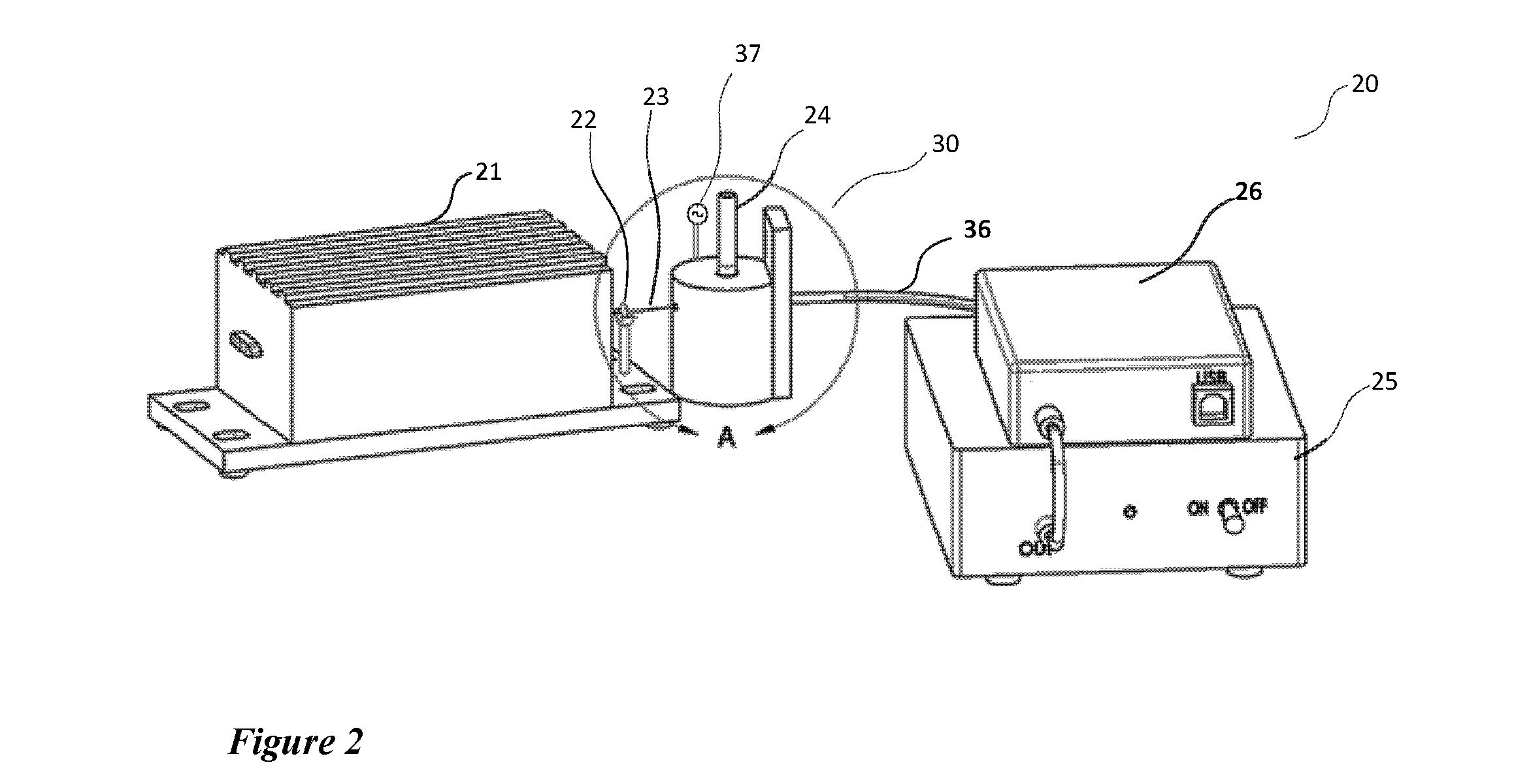
[0122]FIG. 10 shows the application of the device presented in FIG. 2 and the data analysis procedures of the present invention as applied to a yeast cell mixture, with separate measurements using frequencies of 300 kHz and 500 kHz. A sample of Baker's yeast (0.5 gram in 100 ml water) was suspended in water and centrifuged at 2000 g for 10 minutes. The supernatant was discarded and the pellet resuspended (by vortex) in 100 ml of water. The process was repeated once and the suspension was used in the measurements, with other conditions similar to those in FIGS. 8-9. The isolated oscillations were extracted, and the FT (velocity domain) spectra of the oscillations are displayed. Trace 75 represents the spectrum from the application of oscillating field gradient of 300 kHz, while trace 76 is the spectrum resulting from the application of 500 kHz. Peak positions can be seen to depend on the frequency employed.

[0123]Several descriptions, illustrations and examples have been presented to ...


PUM


Abstract

Non-invasive apparatus and method for determining and monitoring glucose concentrations in human subjects. Glucose level is estimated through the effect of glucose on biological cells with glucose dependencies, e.g., red blood cells. The invention is based on the interaction of such cells with oscillating electric field gradients. The response of biological cells depends on factors including shape, size, and electrical charge distribution. The field gradient causes the cells to undergo characteristic motion which is detected by light beam scattering. The autocorrelation of the scattered light is computed, and the Fourier transform (FT) is performed to produce a characteristic velocity spectrum in which the peaks are characteristic of the cell “bio-electrical” states. The glucose level is estimated through measurements of changes of FT with changes in glucose levels after calibration with standard glucose methods.

Description

BACKGROUND OF THE INVENTION[0001]1. Field of the Invention[0002]The present invention relates to measuring a medical parameter and more particularly to a non-invasive glucose measurement device.[0003]2. Description of the Prior Art[0004]Non-Invasive (NI) blood glucose level monitoring has been pursued by many academic and industrial institutions. On-market blood glucose measurements, while achieving remarkable advances in accuracy and minimizing blood sample volume, still require blood draw. Many diabetics harbor anxiety and needle phobia to the point of interfering with timely testing. In spite of numerous publications and proposed devices, NI glucose detection devices usable by diabetics have remained elusive. Diabetes is a long term disease with well-known cardiovascular complications as well as damage to many organs such as the eyes, kidneys, and even causing amputations. A successful NI glucose measurement device would enable more frequent monitoring and compliance with medicat...

Claims


Application Information

Patent Timeline
Patent Type & Authority Patents(United States)
IPC IPC(8): A61B5/1455A61B5/00A61B5/05A61B5/145
CPCA61B5/14532A61B5/0093G01N27/44773A61B5/1455A61B2562/0233A61B5/0507A61B5/05B03C5/005A61B5/7257B03C2201/26B03C5/026G01N33/483
Inventor HALAKA, FOLIM, G.
Owner HALAKA FOLIM G
Why Eureka
Try Eureka