Optical coherence tomography system and method

a tomography and optical coherence technology, applied in the field of detection of signals in an optical coherence tomography system, can solve problems such as reducing imaging depth, wasting resources, and known complex conjugate ambiguity

Active Publication Date: 2014-10-07
II VI DELAWARE INC
View PDF10 Cites 16 Cited by
  • Summary
  • Abstract
  • Description
  • Claims
  • Application Information

AI Technical Summary

Problems solved by technology

In FD-OCT systems the lack of phase information leads to a known complex conjugate ambiguity, where the positive and negative spatial frequencies of the signal cannot be separated.
This complex conjugate ambiguity results in image contamination with double images, undesirable autocorrelation terms and wasted resources (pixels in SD-OCT and time in SS-OCT) due to a reduction in imaging depth.
This results in a complex conjugate ambiguity that cannot be resolved or removed via post processing, necessitating the use of the full complex signal to remove the ambiguity.
In polarization quadrature encoding, orthogonal polarization states encode the real and imaginary parts of the signal, but the setup is complex and the signal suffers from polarization fading as the reference and sample arms approach a quasi-orthogonal state.
However, phase stepping is not instantaneous and sensitive to small drifts in the interferometer.
Relying on an electronic carrier frequency, synchronous detection is unsuitable for homodyne detection systems, such as in FD-OCT setups.
Polarization fading is also a problem for most interferometric systems.

Method used


Image

  • Optical coherence tomography system and method
  • Optical coherence tomography system and method
  • Optical coherence tomography system and method

Examples


example implementations

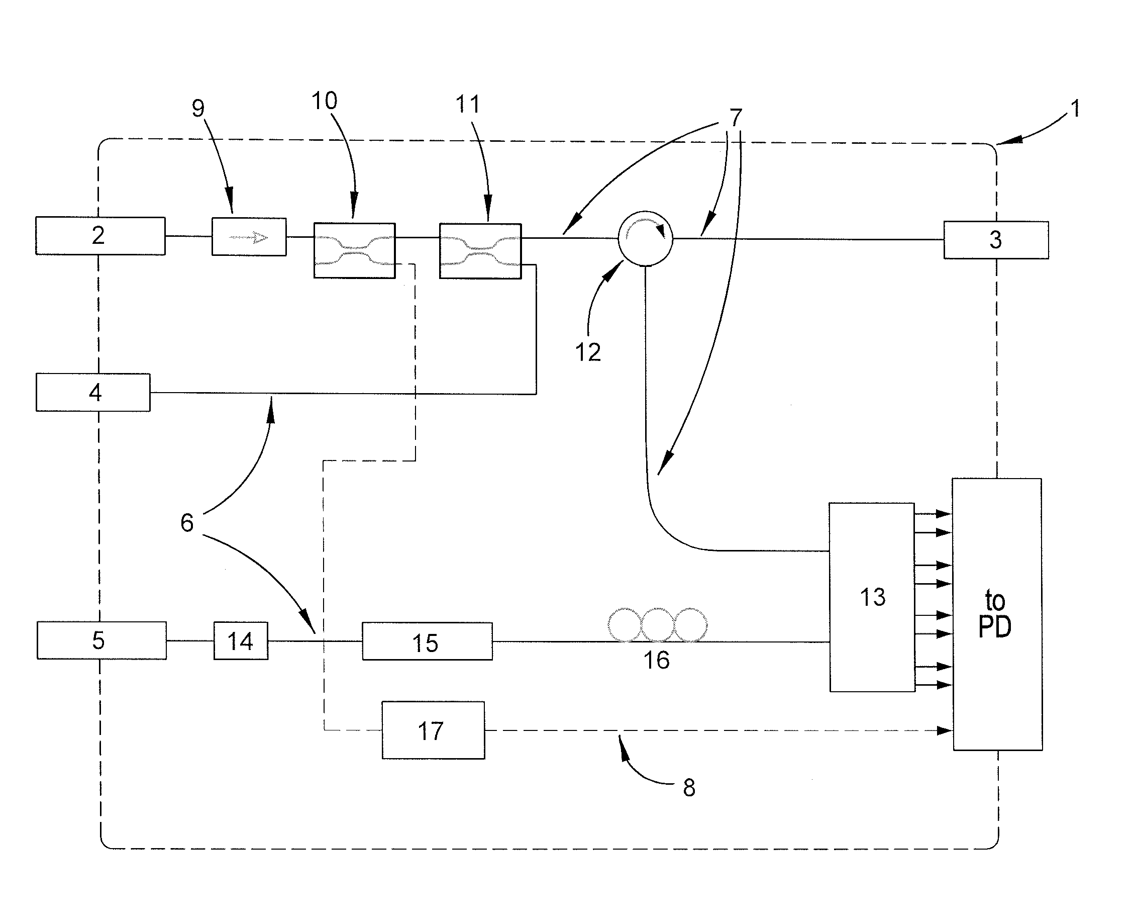
[0081]The integration of the CPA into an OCT system can be seen initially in FIG. 6 and FIG. 7. FIG. 6 and FIG. 7 show example electronic connections.

[0082]Turning initially to FIG. 6, the eight optical output ports of the CPA 13 of the optical engine 1 are connected to four balanced photo-detectors 32, each balanced photo-detector corresponding to a quadrature in each polarization. The use of balanced photo-detectors can eliminate the need for the removal of the DC bias component of the inteferometric signal later on in the processing.

[0083]FIG. 7 illustrates an alternative arrangement showing the use of standard photo-detectors 33 in the system. In this configuration the DC bias is removed later on in the signal processing.

[0084]In either case, the signal is then passed through a data acquisition card (DAQ) 34 which converts the analogue signal into a digital signal and samples it. A further photo-detector 33 connected between the trigger path 8 and the DAQ 34 is used to provide a...

example

No Quadrature Signal Implementation

[0118]The OCT systems described so far can be further simplified at the expense of reduced functionality. By ignoring the quadrature component of the signal, the receiver electronics are reduced and the resulting signal processing simplified. When the quadrature component is ignored, minor modifications to the CPA 13 remove a 3 dB signal loss, due to a further polarization splitting, but still provide the advantages associated with polarization mixing. One such modification to remove the quadrature signal is realized by removing the quarter waveplate 75 and power splitter 120 seen in FIG. 14.


PUM

PropertyMeasurementUnit
optical signal analysisaaaaaaaaaa
path lengthaaaaaaaaaa
optical pathsaaaaaaaaaa

Abstract

A method of analysis of a sample, including the steps of: (a) splitting an input optical beam into a probe beam and reference beam; (b) utilizing the probe beam to interrogate a sample and obtaining a return sample beam there from; (c) manipulating the reference beam into a predetermined polarization state; (d) mixing the return sample beam and reference beam producing a series of mixed beams; and (e) analyzing the polarization components of the series of mixed beams.

Description

CROSS-REFERENCE TO RELATED APPLICATIONS[0001]The present application is a non-provisional of copending U.S. Provisional Patent Application Ser. No. 61 / 414,727, filed on Nov. 17, 2010. The entire contents U.S. Patent Application Ser. No. 61 / 414,727 is herein incorporated by reference.FIELD OF THE INVENTION[0002]The present invention relates to the detection of signals in an optical coherence tomography system. In particular, the invention provides for the simultaneous detection of both polarization and phase resolved signals. The invention includes an optical imaging engine whose modular design allows for simple integration into diverse OCT systems.DESCRIPTION OF THE BACKGROUND ART[0003]Optical Coherence Tomography (OCT) is an imaging technique that allows micrometer scale imaging over short distances. It is based on a novel extension of optical coherence domain reflectometry (OCDR), a one dimensional optical ranging technique used for investigating the properties of fiber and wavegu...

Claims


Application Information

Patent Timeline
Patent Type & Authority Patents(United States)
IPC IPC(8): G01B9/02G01N21/47
CPCG01B9/02069G01B9/02081G01N21/4795G01B9/02004G01B9/02091G01B2290/45G01B2290/70
Inventor FRISKEN, STEVEN JAMESNEILL, DANIEL ROYSTON
Owner II VI DELAWARE INC
Why Eureka
Try Eureka