Process for reducing sulfur emission of sulfur plant

a sulfur plant and sulfur technology, applied in the field of sulfur recovery, can solve the problems of low sulfur emission rate, fragile solid sulfur formed from undegassed sulfur, and severe restrictions on sulfur emission in developed countries, and achieve the effect of low operating cost and small investmen

Active Publication Date: 2014-10-28
CHINA PETROCHEMICAL CORP
View PDF18 Cites 42 Cited by
  • Summary
  • Abstract
  • Description
  • Claims
  • Application Information

AI Technical Summary

Benefits of technology

[0011]One of the technical problems to be solved in present invention is to reduce the SO2 emission concentration of a sulfur plant, wherein the SO2 emission content can be decreased to not more than about 100 mg / m3, preferably not more than about 80 mg / m3. A process for solving this technical problem is provided in present invention, which process needs a small investment, has a low operating cost and is environment-friendly and energy-saving.
[0017]An aspect of present invention relates to the introduction of waste-gas from the degassing of the liquid sulfur into the catalytic reaction unit, and / or the tail-gas purification unit. The introduction of the waste-gas into the incinerator and the discharging after burning thus are avoided and sulfur emission is reduced. Another aspect of present invention relates to a feature or improvement wherein a portion of the purified tail-gas is used as stripping gas for the liquid sulfur tank, and thus the use of air, nitrogen or steam is omitted. According to another aspect of present invention, in the process of present invention, a portion of the purified tail-gas is used as stripping gas for the liquid sulfur tank, and the resulting waste-gas from the degassing of the liquid sulfur is mixed with the Claus tail-gas and then introduced into hydrogenation reactor of the tail-gas purification unit. These features or improvements according to present invention decrease the SO2 emission concentration of sulfur recovery plant efficiently.

Problems solved by technology

Sulfur emission is severely restricted in developed countries.
When H2S accumulates to a certain concentration, it will cause toxic action or even has a possibility of explosion.
In another aspect, solid sulfur formed from undegassed sulfur is fragile, producing more fine particles and powder of sulfur during loading and unloading and transportation.
Steam can lead to corrosion of pipes and equipments easily.
Nitrogen has low oxygen content and thus is not favorable for the oxidation of sulfur-containing compounds.
However, the amount of gas to be processed will be increased due to the use of an external gas-source, leading to enlargement of pipes and equipments.

Method used


Image

  • Process for reducing sulfur emission of sulfur plant
  • Process for reducing sulfur emission of sulfur plant
  • Process for reducing sulfur emission of sulfur plant

Examples


example 1

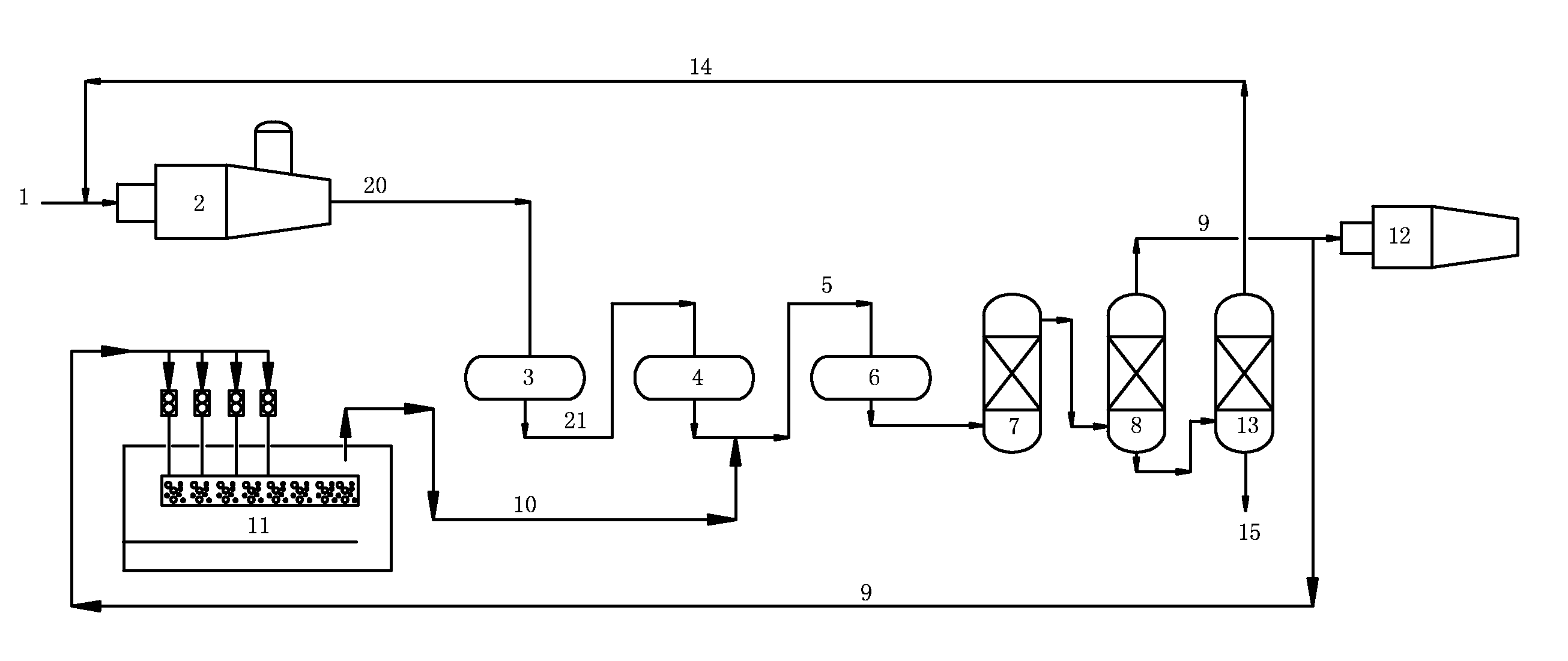
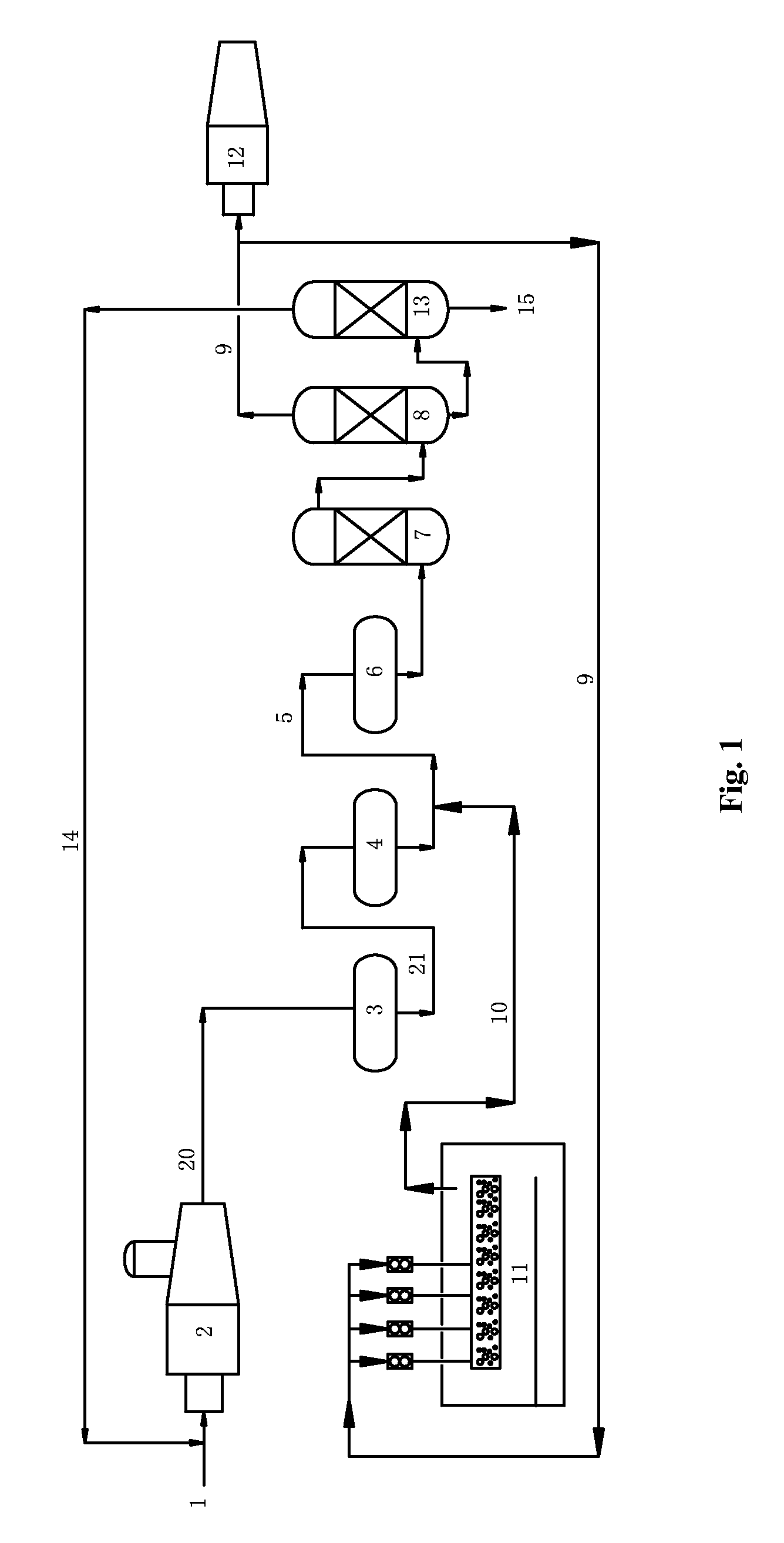
[0080]The procedure of this example was as illustrated FIG. 1. This procedure included thermal reaction section, catalytic reaction section and tail-gas purification section.

[0081]In the thermal reaction section, acid gas (1) comprising 90 (v / v) % of H2S was partially combusted in the reaction furnace (2), wherein about one third of H2S was converted into SO2. At 1250° C., H2S reacted with SO2 according to Claus reaction so as to produce element sulfur and a process gas (20), wherein the element sulfur was sent to liquid sulfur tank (11) to obtain liquid sulfur. This process gas (20) comprised, by volume, H2S 6%, SO2 2.5%, organo-sulfur compounds 0.5%.

[0082]The process gas (20) was introduced into the first converter (3) (operation conditions: 300° C., space velocity 800 h−1) and then the second converter (4) (operation conditions: 250° C., space velocity 800 h−1) of the catalytic reaction section. After the Claus catalytic conversion (in the presence of alumina-based Claus catalyst...

example 2

[0086]The procedure of this example was as illustrated FIG. 1. This procedure included thermal reaction section, catalytic reaction section and tail-gas purification section.

[0087]In the thermal reaction section, acid gas (1) comprising 75 (v / v) % of H2S was partially combusted in the reaction furnace (2), wherein about one third of H2S was converted into SO2. At 1250° C., H2S reacted with SO2 according to Claus reaction so as to produce element sulfur and a process gas (20), wherein the element sulfur was sent to liquid sulfur tank (11) to obtain liquid sulfur. This process gas (20) comprised, by volume, H2S 8%, SO2 3%, organo-sulfur compounds 1%.

[0088]The process gas (20) was introduced into the first converter (3) (operation conditions: 320° C., space velocity 800 h−1) and then the second converter (4) (operation conditions: space velocity 250° C., 800 h−1) of the catalytic reaction section. After the Claus catalytic conversion (in the presence of alumina-based Claus catalyst—LS-...

example 3

[0092]The procedure of this example was as illustrated FIG. 1. This procedure included thermal reaction section, catalytic reaction section and tail-gas purification section.

[0093]In the thermal reaction section, acid gas (1) comprising 55 (v / v) % of H2S was partially combusted in the reaction furnace (2), wherein about one third of H2S was converted into SO2. At 1250° C., H2S reacted with SO2 according to Claus reaction so as to produce element sulfur and a process gas (20), wherein the element sulfur was sent to liquid sulfur tank (11) to obtain liquid sulfur. This process gas (20) comprised, by volume, H2S 4%, SO2 2%, organo-sulfur compounds 0.3%.

[0094]The process gas (20) was introduced into the first converter (3) (operation conditions: 320° C., space velocity 800 h−1) and then the second converter (4) (operation conditions: 250° C., space velocity 800 h−1) of the catalytic reaction section. After the Claus catalytic conversion (in the presence of alumina-based Claus catalyst—L...


PUM

PropertyMeasurementUnit
concentrationaaaaaaaaaa
temperatureaaaaaaaaaa

Abstract

The present invention provides a process for reducing sulfur emission of a sulfur plant, wherein the sulfur plant includes a thermal reaction unit, a catalytic reaction unit and a tail-gas purification unit, the process is characterized in that the waste-gas from the degassing of the liquid sulfur in the liquid sulfur tank is introduced into the catalytic reaction unit, and / or the waste-gas from the degassing of the liquid sulfur in the liquid sulfur tank is introduced into the tail-gas purification unit. In present invention, the H2S in purified tail-gas can be reduced to no more than 10 ppm(v) and the SO2 emission concentration of the sulfur plant can be reduced to no more than 100 mg / m3.

Description

[0001]The present application claims the priority of China Patent Application No. 201210349499.8 filed on Sep. 19, 2012, which is incorporated herein by reference in its entirety.TECHNICAL FIELD[0002]The present invention relates to the filed of sulfur recovery, in particular to a process for reducing the sulfur (for example SO2) emission of a sulfur plant.BACKGROUNDS[0003]With the development of society, environmental pollution has become a restrict factor of economic development and is an important section in government legislation. Sulfur emission is severely restricted in developed countries. For example, according to the regulations of Environmental Protection Agency of The Federal Government of the United States, the SO2 emission in furnace flue gas, sulfur tail-gas and catalytic cracking regeneration flue gas in petroleum refining industry is limited to 50 ppm(v), equaling to about 143 mg / m3.[0004]New techniques for tail-gas treatment of Claus sulfur recovery are under develo...

Claims


Application Information

Patent Timeline
Patent Type & Authority Patents(United States)
IPC IPC(8): C01B17/05C01B17/02C01B17/04
CPCC01B17/05C01B17/043C01B17/0232C01B17/04C01B17/021C01B17/0456C01B17/0426
Inventor LIU, AIHUAXU, YONGCHANGLI, QINSHUREN, JIANBANGLIU, JIANLIZHANG, YILING
Owner CHINA PETROCHEMICAL CORP
Why Eureka
Try Eureka