
Self fixing spinal cord stimulation paddle lead

a technology of spinal cord and paddle lead, which is applied in the field of implantable medical electrical leads, can solve the problems of difficult to stimulate the targeted neurological tissue in an energy-efficient manner, confined spaces of the spinal column, and many problems that have yet to be optimized, so as to improve the directional control of the stimulation signal and increase the energy efficiency of the medical devi

Active Publication Date: 2014-10-28
CIRTEC MEDICAL CORP
View PDF35 Cites 0 Cited by
  • Summary
  • Abstract
  • Description
  • Claims
  • Application Information

AI Technical Summary

Benefits of technology

The present invention is a paddle lead designed to address the shortcomings of the prior art. The double curved flexible paddle assembly design improves energy efficiency and provides better directional control of the electrical signal. The concave surface of the left side paddle expands and conforms to the contours of the fetal spinal cord, and the embedded electrodes in the surface of the left paddle compress into the dura mater of the spinal cord, thereby providing improved directional control of the stimulation signal. Compression of the paddle into the neurological tissue restricts the flow of cerebrospinal fluid which increases the energy efficiency of the medical device.

Problems solved by technology

Despite the many advances in neurostimulation, many problems still exist with the technology that have yet to be optimized.
However the geometric constraints of the human anatomy sometimes make it difficult to stimulate the targeted neurological tissue in an energy efficient manner.
The confined spaces of the spinal column add an increased element of complexity to neurological tissue stimulation.
In addition, the delicate nature of the neurological tissue make lead fixation challenging.
However, despite their advantages of implantation, percutaneous leads are often ineffective in targeting specific neurological tissue in an energy efficient manner.
This approach does not efficiently utilize the electrical energy of the medical device.
As a result of the indiscriminately broadcasted energy, a power burden is placed on the implanted medical device.
Percutanous leads also lack a fixation mechanism which makes them prone to movement within the body.
However, a disadvantage to the traditional paddle lead is that they are typically designed with a top and bottom planar surface that do not conform to curved surfaces.
This is not an ideal shape for focusing electrical energy to a specific location located around a cylindrical spinal column and spinal cord.
Unfortunately, this shape alone without a fixation mechanism, would allow for the paddle body to rotate in the epidural space of the spinal column with little resistance.
Paddle leads lack a fixation mechanism and therefore are susceptible to lead migration.
However the winged electrode body design by Jordan is one rigid piece that lacks a fixation mechanism.
This kind of movement could cause the paddle electrode to move further away from the target nerve and possibly result in an increase in the amount of cerebrospinal fluid (CSF) between the electrode and target nerve.
An increase in CSF between the electrodes and targeted neurological tissue is not desired because it decreases the electrical efficiency of the system.

Method used


Image

  • Self fixing spinal cord stimulation paddle lead
  • Self fixing spinal cord stimulation paddle lead
  • Self fixing spinal cord stimulation paddle lead

Examples


Embodiment Construction

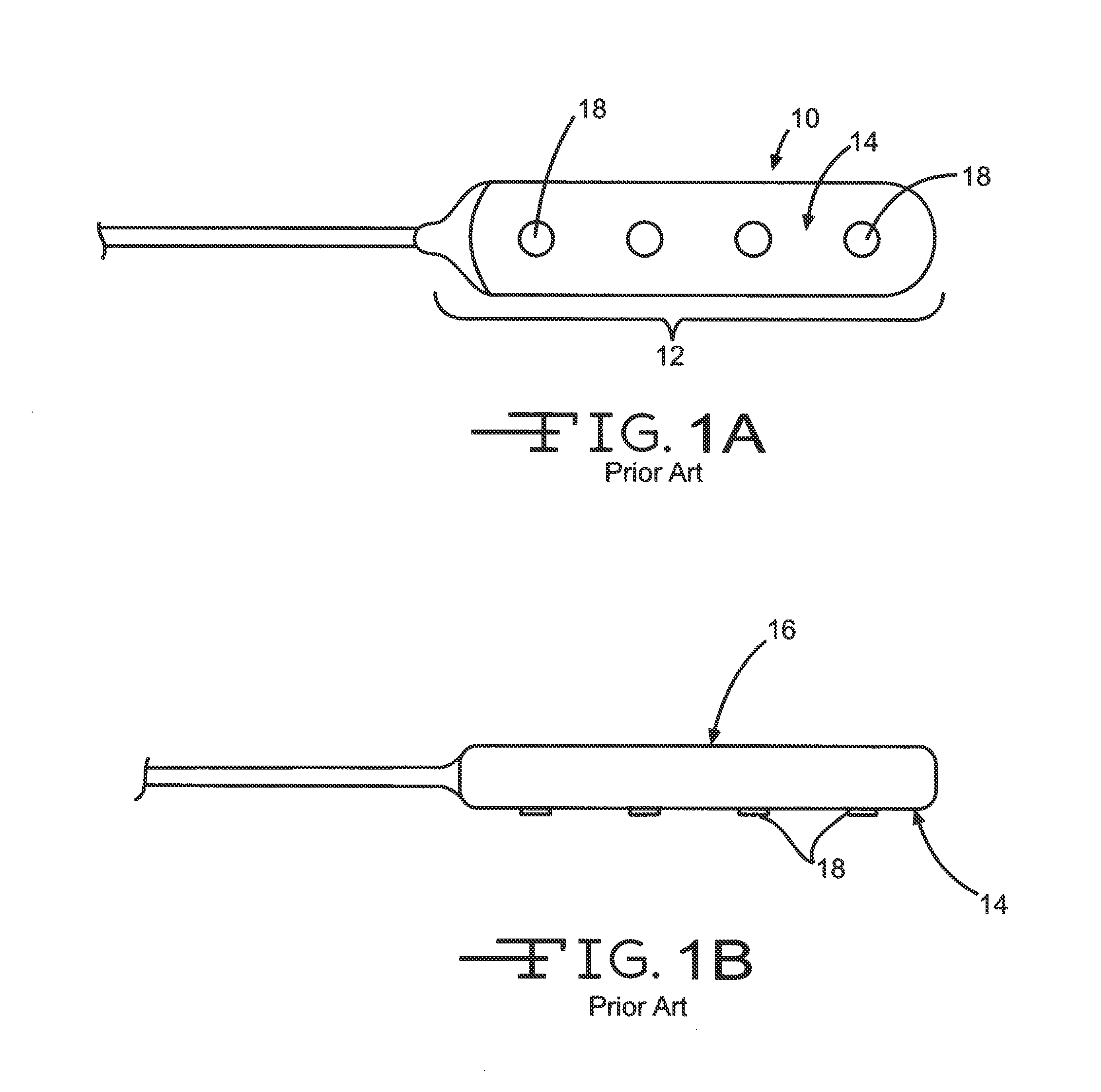
[0028]FIGS. 1A and 1B show an example of a traditional prior art paddle lead 10. The distal end of the lead 12 has an extension that resembles a paddle. The distal extension is typically a rectangular body with a planar top surface 14 and a planar bottom surface 16. Electrodes 18 are embedded within the top surface 14. As previously mentioned, this lead design is not optimized to fit properly in the curved confines of the epidural space between the spinal column and the dura mater and, as such, does not provide an efficient means to direct electrical energy to stimulate the spinal cord. In addition, this lead design lacks an anchoring mechanism to prevent the distal end from migrating in the epidural space.

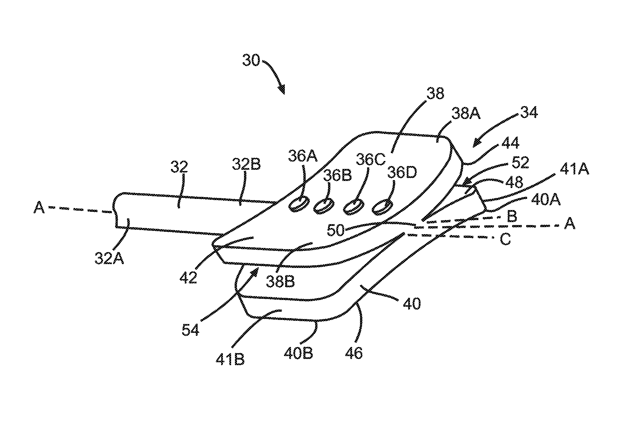
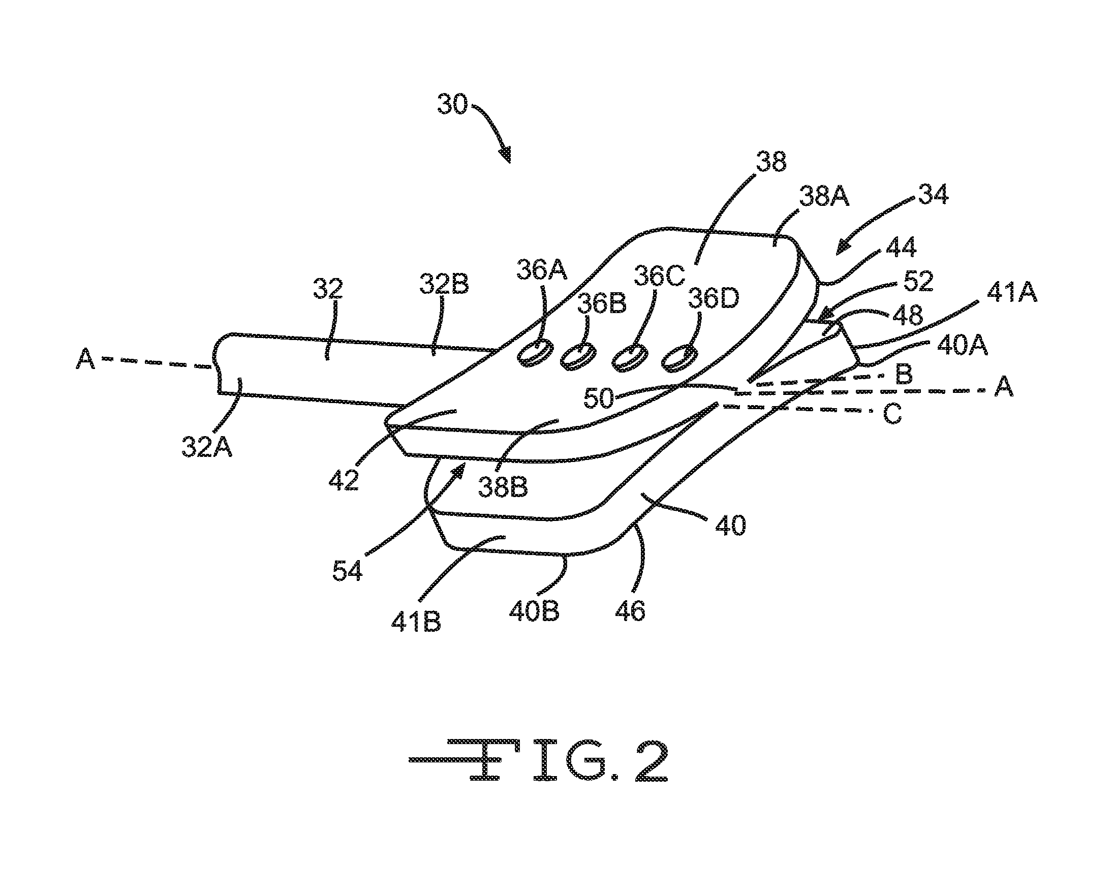
[0029]FIG. 2 illustrates an electrode 30 according to the present invention. Electrode 30 is comprised of a lead body 32 and a paddle body assembly 34. As FIG. 2 shows, the paddle body assembly 34 is attached to the distal region 32B of the lead body along a longitudinal axis A-A....


PUM


Abstract

An improved electrical neurological stimulation paddle lead is described. The paddle lead comprises two flexible concave paddle bodies that are joined together at their opposing convex surfaces. The first paddle body contains a series of electrodes that are embedded on the concave surface that expand to fit the contours of the dura mater. The second paddle body consists of a concave surface that is pressed against the bone of the spinal column to act as a fixation mechanism to keep the paddle assembly in place.

Description

CROSS-REFERENCE TO RELATED APPLICATION[0001]The present application claims priority from U.S. Provisional Application Ser. No. 61 / 121,966 filed Dec. 12, 2008.BACKGROUND OF THE INVENTION[0002]1. Field of the Invention[0003]The present invention is related generally to implantable medical electrical leads. More specifically, the present invention is related to implantable neurological leads.[0004]2. Prior Art[0005]Neurostimulation is the application of electrical energy to neurological tissue to block the sensation of pain. A medical device, specifically an implanted neurostimulator generates an electrical pulse which is emitted from a connected lead that is implanted in the body.[0006]Despite the many advances in neurostimulation, many problems still exist with the technology that have yet to be optimized. One of which is lead migration, the second being energy efficiency.[0007]An ideal neurostimulation lead is designed to remain in position and emit electrical energy to a specific t...

Claims


Application Information

Patent Timeline
IPC IPC(8): A61N1/05A61B5/042
CPCA61N1/0551A61B5/042A61N1/0553A61N1/0558
Inventor SWOYER, JOHN M.KOKONES, SCOTT
Owner CIRTEC MEDICAL CORP
Features
  • Generate Ideas
  • Intellectual Property
  • Life Sciences
  • Materials
  • Tech Scout
  • Unparalleled Data Quality
  • Higher Quality Content
  • 60% Fewer Hallucinations
Learn More